|
1. INTRODUCTIONS
With the widely known advantages of Carbon Fiber Reinforced Polymer, or CFRP in short, such as lightweight, high strength and good ductility, it has good application future in large span structures. At present a feasible application of CFRP in large span structures is using CFRP as cables to replace steel in cable supported structures (Mei & Lu 2004). However, since the density of CFRP is very small, which is only about 1/5 of steel, the wind-induced vibration may be an important control state in the design of CFRP cables. Because of the small lateral stiffness of cables, there are many reports on the damage or failure of steel cables due to wind-induced vibration. And the weight of CFRP cables is smaller than the steel cable while the span of CFRP cables may be larger than the steel cables. So more studies should be given to the wind-induced vibration of CFRP cables.
Though currently great development has been achieved in the structural wind engineering with wind-tunnel tests and random vibration theory, because of the extremely large size of buildings compared to airplanes, the size effect of wind tunnel test will be more serious than that in aeronautical engineering. Furthermore, when the structure-wind coupled vibration needs to be considered, the similarity ratio design will be very complicated in wind tunnel tests. Besides that, the wind tunnel test is expensive in many cases. Hence, the fluid-solid coupled numerical simulation, which integrates the latest progress of Computational Fluid Dynamics (i.e. CFD) and Computational Structural Dynamics (i.e. CSD), will have good future on structural wind engineering (Huang 2001, Wu 2003). Due to the limitation of hardware, software capacity, most of existing fluid-solid coupled numerical simulations for structures are 2-D simulations (Wu 2003). With the progress of computer hardware and software, 3-D fluid-solid coupled numerical simulation for structures is feasible now. Hence, with the common purpose FE software of ANSYS, 3-D fluid-solid coupled numerical simulation is implemented for the wind-vibration of CFRP cables. The parameters and models for the simulation are discussed, and the results of CFRP cables are compared with steel cables.
2. FLUID-SOLID COUPLED SIMULATION IN ANSYS
2.1 Fundamental Conceptions
Normally, there are three different components in fluid-solid coupled numerical simulation: (1) Fluid field (CFD); (2) Structural field (CSD) (3) Interface between fluid and structures (Wu 2003).
The flow chart for coupled field simulation is shown as follows:
(1) The un-deformed shape of structures is treated as the boundary of fluid, and the pressure on the surface of structure is calculated with the CFD simulation.
(2) The pressure from the fluid field is acted on the surface of the structures to obtain the structural deformation. Then, the boundary of fluid is updated with the deformed shape of structure, and the CFRP simulation is repeated with new boundaries.
(3) Step (1) and Step (2) is iterated until the pressure change in the fluid-solid interface between two iterations is smaller than the error tolerance.
For most structures in civil engineering, the displacement is relative small even large displacement effect is considered. So the mesh adaptation in the fluid-solid interface is not very complicated if with proper initial mesh. And the CSD simulation has been very mature now. Thus, the major difficulties for coupled simulation are located in the fluid field. As lots of civil engineering structures are blunt bodies, how to properly simulate the pressure and velocity of the fluid that surround the structures is a tough challenge to current CFD simulation.
2.2 Fluid Models in ANSYS
The fluid model in ANSYS is based on the Reynolds Average Navier-Stokes (RANS) equations (Huang 2001), whose kernel advantage is that the transient Navier-Stokes equations are replaced with the Reynolds average equations, which will effectively reduce the computational effort for eddy simulation. This model has been used widely in engineering and it is also a relatively mature model for turbulence simulation.
Since RANS needs to model the transient eddy with averaged turbulence models, a proper turbulence model will be a key problem for RANS simulation. Existing researches show that various turbulence models will give extremely different results for the same problem, especially for such blunt bodies like structures in civil engineering (Huang 2001). Seven different turbulence models have been provided in ANSYS, which are: (1) Standard k-e model (i.e. SKE model); (2) Re-Normalized Group Turbulence model (i.e. RNG model); (3) k-¦Ĺ Model due to Shih (i.e. NKE model); (4) Nonlinear Model of Girimaji (i.e. GIR model); (5) Shih, Zhu, Lumley Model (i.e. SZL model) (6) k-¦Ř Turbulence Model (i.e. SKW model); (7) Shear Stress Transport Turbulence Model (i.e. SST model)
The Standard k-e has been proved that though it is used mostly widely, it is not suitable for fluid passing blunt bodies (Tsuchiya et al. 1997). And the RNG model has been received more attentions in computational wind engineering in recent years (Murakami 1998). Hence, in order to achieve a better understanding for the turbulence models in ANSYS, benchmark comparisons are implemented firstly to these models.
Three fundamental benchmarks are selected to compare different turbulence models, and the results of different benchmarks are illustrated as follows:
(a) Wind pressure on a square house. The comparison between wind-tunnel tests (Tsuchiya et al. 1997) and numerical results shows that the simulation generally agrees well with the test but large errors are seen on the upwind side of the roof. And RNG, GIR, SZL and SKW models provide relatively better results, while SKE model provides the worst one.
(b) Wind passes a square cylinder. From the comparison between wind-tunnel tests (Murakami & Mochida 1995) and numerical results it can be found that the results of SZL model and GIR model are relatively close to the tests.
(c) Wind passes a round cylinder. The comparison between wind-tunnel tests (Huang 2001) and numerical results shows that on the surface normal to the wind, all models provide good results. However, the wind pressures on the across side of cylinder are smaller than the test for all models, while SST, SKW and SKE models are more acceptable. If the contour of wind speed is compared with the test, it will be found that RNG, GIR and SZL models provide closer result with the test while others are worse.
In order to discuss the difference of models in the fluid-solid coupled simulations, these turbulence models need to be further benchmarked with coupled problems. However, because standard fluid-solid coupled test is hardly to be found from the existing literatures, a plate in fluid, which introduced by Gluck et al. (2001) to proof the coupled simulation, is selected as a benchmark for the model comparison. From the comparison it is clearly found that the results of RNG and SZL models are the closest to those in Gluck et al.ˇŻs work (2001).
Thus, a general review of all above comparisons for different models is show in Table 1. From the table it can be found that for the coupled vibration problem that will be studied in this paper, RNG model and SZL model seem to be more suitable than other models and this conclusion also consists with some other researches.
Table 1 Comparison for the results with different turbulent models
| |
SKE |
RNG |
NKE |
GIR |
SZL |
SKW |
SST |
| |
ˇÁ |
ˇî |
ˇ÷ |
ˇî |
ˇî |
ˇî |
ˇ÷ |
| Wind passes square cylinder |
ˇÁ |
ˇÁ |
ˇÁ |
ˇ÷ |
ˇî |
ˇÁ |
ˇÁ |
| Wind passes round cylinder (Pressure) |
ˇî |
ˇÁ |
ˇ÷ |
ˇÁ |
ˇÁ |
ˇî |
ˇî |
| Wind passes round cylinder (Velocity) |
ˇÁ |
ˇî |
ˇÁ |
ˇî |
ˇî |
ˇÁ |
ˇÁ |
| Coupled simulation |
ˇî |
ˇî |
ˇÁ |
ˇÁ |
ˇî |
ˇÁ |
ˇ÷ |
Notice: ˇî: Good; ˇ÷: Acceptable; ˇÁ: Poor
3. WIND-INCLUDED VIBRATION OF CFRP Cables
3.1 Computational Model
A CFRP cable with 100m in length, 10 cm in diameter is select to study its wind-induced vibration behavior. The elastic modulus of the CFRP cable is 230GPa, and the density is 1400kg/m3. Two pre-stress conditions, which are 200MPa and 500MPa respectively, are simulated. In order to consider the interaction between CFRP cable and the air around it, an air column around the cable, with 4mˇÁ10mˇÁ100m in size, is also modeled with CFD. The whole computational model is shown in Figure 1.
A stable wind field and 3 fluctuant wind fields are inputted in the model with the average wind speed of 30m/s. And the results of CFRP cables are compared with steel cables.
   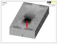
(a) Model dimension (b) Finite element mesh (Part)
Figure 1 Computational model for the wind-induced vibration of CFRP cable
3.2 Results of Stable Wind Field
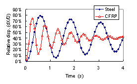
The two pre-stressed conditions, 200MPa and 500MPa, are computed with the RNG model and SZL model to study the wind-induced vibration of CFRP cables and steel cables with fluid-solid coupled simulation. The results show that there is almost no difference between the two turbulence models. The time-history curves of the maximal deformations of CFRP cables with SZL model when pre-stress equals to 200MPa are shown in Figure 2. Following conclusions can be obtained from the curves:
| 
|
|
| Figure 2 The time-history curves of maximal relative deformation of cables in stable wind field, pre-stress=200MPa (dX is the maximal deformation of the cable, D is the diameter of the cable) |
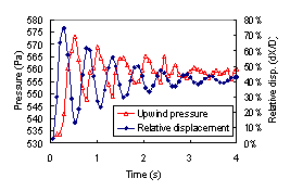
Figure 3 The time-history curves of wind pressure and deformation of CFRP cables, pre-stress=200MPa |
(1) The aerodynamic damping effect is obvious in the figures. Though no additional damping is considered in the numerical model, due to the influence of air around the cables, both steel cable and CFRP cable show the reduction of vibration with time. Take the CFRP cable as an example, the wind pressures on the upwind surfaces of the cables are shown in Figure 3 with the deformations of the cables. It can be found that there is an obvious reaction force on the cable from the surrounding air. And if the amplitude or the frequency of the vibration is larger, the reaction force of the air will be stronger. Thus, considering the aerodynamic damping of the air, it can be found from the numerical results that: for CFRP cable, with 200MPa pre-stress, the damping ratio is about 0.053. And when the pre-stress is increased to 500MPa, the damping ratio will increase to about 0.11 due to the faster vibration with larger pre-stress. The same phenomenon is also seen for steel cable. With pre-stress of 200MPa, the damping ratio of steel cable is about 0.015. And the damping ratio increases to 0.067 with the pre-stress of 500MPa.
(2) The vibration frequencies of the cable from the numerical results are compared with the theoretical ones as shown in Table 2. It can be found from the table that all the frequencies from numerical models are a little bitter smaller than the theoretical ones. That means when the fluid-solid coupled effect is considered, the air around the cables will vibrate together with the cables. So the aerodynamic mass reduces the frequencies of the cables. And because the density of CFRP is smaller than steel, the influence of the mass of air surrounding the CFRP cables will be more obvious than that of steel cables. So the differences between theoretical and numerical frequencies of CFRP cable are larger than that of the steel cables. However, the differences between theoretical and numerical frequencies are all smaller than 5%, for both CFRP cables and steel cables, which means that the aerodynamic mass and aerodynamic stiffness are all very small for the cables.
(3) In this study, the vibration of the cable is mainly along-wind vibration while the across-wind vibration is very small. The reason for this problem is mainly because with current turbulence model, the wind pressure on the side of the cable is not accurate enough.
Table 2 Free vibration frequencies of cables (First mode)
| Pre-stress |
Numerical frequencies (Hz) |
Theoretical frequencies
(Without damping) (Hz) |
Theoretical frequencies
(With damping) (Hz) |
| |
CFRP cable |
Steel cable |
CFRP cable |
Steel cable |
CFRP cable |
Steel cable |
| 200MPa |
1.810 |
0.779 |
1.890 |
0.801 |
1.887 |
0.800 |
| 500MPa |
2.807 |
1.233 |
2.99 |
1.266 |
2.97 |
1.266 |
|
|
|
|
|
|
|
|
3.3 Results of Fluctuant Wind Field
Three fluctuant wind fields are created with the Davenport wind power spectrum. The vibration of steel cables and CFRP cables in fluctuant wind field is simulated and the time-history deformation curves of cables are counted and the frequency distributions of the deformations are fitted with normal distribution functions. And the average value and standard deviation of different curve fittings are shown in Table 3. From the table it can be found that for cables with 200MPa pre-stress, the standard deviation of deformation of both CFRP cable and steel cable are relatively large. And we can hardly find which one is better. However, when pre-stress is increased to 500MPa, the standard deviations of CFRP cables are smaller than those of the steel ones. Two reasons can be found to explain this phenomenon: (a) The frequency of CFRP cable is larger due to the density of CFRP is smaller, so less fluctuant wind energy in low frequency zone will be absorbed by the CFRP cable; (b) The aerodynamic damping of CFRP cable is larger than that of the steel cable, so more energy will be consumed for CFRP cables in the vibration. Hence, though it is usually considered that the wind-induced vibration of CFRP cables should be more serious than steel cable due to its lightweight, with proper design, the wind performance of CFRP cables may be better than steel cables.
Table 3 Statistic results of relative deformation of cables in fluctuant wind field
| Pre-stress |
Fluctuant wind records |
CFRP cables |
Steel cables |
| Mean |
STD* |
STD/Mean |
Mean |
STD* |
STD/Mean |
| 200MPa |
01 |
0.395 |
0.228 |
0.577 |
0.399 |
0.295 |
0.739 |
| 02 |
0.403 |
0.245 |
0.608 |
0.397 |
0.284 |
0.715 |
| 03 |
0.386 |
0.295 |
0.764 |
0.392 |
0.234 |
0.597 |
| 500MPa |
01 |
0.156 |
0.066 |
0.423 |
0.159 |
0.084 |
0.528 |
| 02 |
0.158 |
0.063 |
0.399 |
0.158 |
0.089 |
0.563 |
| 03 |
0.154 |
0.077 |
0.500 |
0.158 |
0.109 |
0.690 |
* STD: Standard deviation
4. CONCLUTIONS
The wind-induced vibration of CFRP cable is studied with fluid-solid coupled simulation function of ANSYS. Following results can be obtained:
(1) The RNG and SZL turbulence models are most suitable for studying the wind-induced vibration of cables among the turbulence models in ANSYS. (2) In stable wind field, the aerodynamic damping of CFRP cable is obvious, while the aerodynamic mass and aerodynamic stiffness are slight. (3) The aerodynamic damping of CFRP will be larger than the one of steel cable with the same size and pre-stress. And the aerodynamic damping effect will be more obvious with larger pre-stress. (4) In fluctuant wind field, with proper design, the wind performance of CFRP cable may be better than steel cable. That is because the vibration and the aerodynamic damping frequency of CFRP cable are larger than that of the steel cable with the same size and pre-stress. This phenomenon is important for the application of CFRP cable in large span structures.
|