Earthquake Disaster Simulation for an Urban Area, with GIS, CAD, FEA and VR Integration

Feng Xu, Xuping Chen, Aizhu Ren and Xinzheng Lu

Dept. of Civil Engineering, Tsinghua University, Beijing 100084, China

Proc. 12th Int. Conf. on Computing in Civil and Building Engineering, Oct. 2008, Beijing, CDROM

Download PDF version

Abstract: For a disaster whose scale includes an urban area, it is difficult to study it with physical experiments. Thus, numerical simulation is a very efficient tool for such problem. This paper aims at developing an integrated urban earthquake simulation system (UESS) that uses GIS as the model source, CAD as the model generating tools, FEA as damage prediction and VR as the post-process platform. An automatic procedure is developed to buildup the 3D structural model of buildings in an urban area, as well as to simulate their earthquake performances, from the digital map of GIS. And the simulation results are presented in an integrated interface with a GIS view-port for position finding, a CAD view-port for 3D structural damage identification and a VR view-port for 3D dynamic structural vibration display. An urban example with more than 7000 buildings is select to demonstrate the feasibility of proposed system.

Key Words: Earthquake simulation; Virtual Reality; integration; Vega; VRGIS


1 Introduction

Disasters such as earthquake will bring damages to a large scale, such as an urban area. It is difficult to study such a large scale disaster with physical experiments. This paper aims at developing a GIS, CAD, FEA and VR integrated environment in the computer, so that the behavior of a disaster and its damages to the urban area can be automatically modeled, simulated, and displayed. The key problems that need to be overcome to develop such a system includes the automatic 3D building model generation from the GIS database, the data integration in different platform, and the real-time dynamic display for the vibration of the buildings.

Existing related researches include: Rick et al. [1] proposed a static simulation solution during developing Karma system on the problem of the data consistency of a CAD model and a GIS model. Hutchinson et al. [2] developed an interactive virtual environment with 2D and 3D technologies to view the building vibration behavior, but it can only deal with a single building. However in an urban area there are a big number of buildings. James [3] deems that the integration of CAD and GIS provides a big potential for the control of whole and part of a project at the same time.

This paper presents an integrated urban earthquake simulation system (UESS) that uses GIS as the model source, CAD as the model generating tools, FEA as damage prediction and VR as the simulation platform. UESS generates the 3D structural model in an urban area automatically and passes them to the structural simulation to predict the damage due to a specified earthquake, and finally the performances of buildings are displayed in an integrated environment, furthermore, the spreading of the earthquake-induced  fire can be simulated.

2 System Framework

UESS is designed in an integrated interface which extracts 2D entities that present the outlines of a building from a digital city map in a GIS environment, sets up 3D building models automatically in a CAD environment, analyzes earthquake vibration behavior in a finite element program and represent the simulation behavior in a virtual reality environment. Its development environments includes ArcGIS Engine 9.0, AutoCAD ObjectARX 2002, Multigen OpenFlight API, and Multigen Vega 3.7. Fig. 1 shows the schematic diagram of UESS.


Fig.1·System architecture of UESS


Fig.1System architecture of UESS


Erect-Up is an automatic model generating module, which reads outline and height information of buildings from a digital city map via ArcGIS Engine, and constructs the 3D model in a CAD environment automatically via AutoCAD ObjectARX. Because Multigen Vega only supports OpenFlight file type, the AutoDesk DWG file is converted into Multigen OpenFlight file with Polytrans, a Multigen OpenFlight API. Erect-Up module also generates the input text file for the time-history seismic structural analysis.

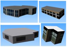
Auto-Texture accesses the database of OpenFlight via OpenFlight API and automatically pastes the textures onto the 3D models according to the scales of the side faces of a building.

The output data of structural analysis in an earthquake is tremendous. For the demonstrate case, more than 7000 buildings and houses in the urban area of Santou City were computed for a 40 seconds earthquake record, with a output interval of 0.1s, the final total output file rows can rise up to tens of millions. Thus in the simulation phase, it will be difficult to do real-time search even with high-performance computers.

So Pre-Simulation module is needed to provide the pretreatment function which picks up the vibration data of each building from the structural analysis output file, and then the results are stored in a temporary file in the sequence of spatial and time order. The simulation process gets the corresponding data only by reading these files rather than searching in the database, which greatly reduces resource consumption. Pre-simulation module also searches the maximal displacement of each building and represents it with gradual color contour.

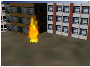
VR-Earthquake module sets up the relationship between the 3D building model and its corresponding seismic vibration response, and represents the vibration in the VR platform. The simulation of fire and smoke effects and the application of VR equipments such as 3D mouse are also achieved with VR-Earthquake module.

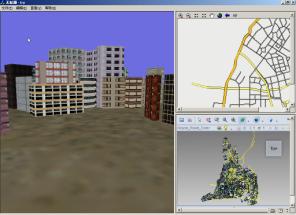
 Integrated-View module presents VR, GIS and CAD with three separated view-ports in an integrated interface. VR view shows the execution of VR-Earthquake module, GIS view shows GIS map via MapControl supplied by ArcGIS Engine, CAD view shows the various damage level of buildings in 3D CAD scenario with different colors via DWFViewer from AutoDesk. The whole module is developed with MFC support.

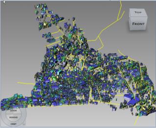
3 Automatic Model Generation and Texture Mapping

It is a heavy workload to generate building models manually for an urban area with thousands of buildings. To solve this problem, an automatic model generation 
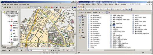
function is developed in UESS to transform the 2D GIS digital map to 3D structural model. The digital urban map in ArcGIS is shown in Fig. 2. By accessing ArcGIS database and searching the 2D polygons of buildings, the outlines 
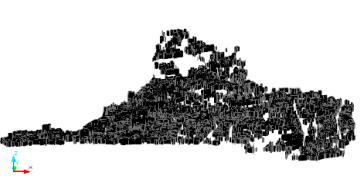
of buildings can be obtained. Then these 2D outlines are extruded to 3D model according to the building height property in the GIS database. With similar method, the models of roads and rivers can also be generated automatically with no heights. The program to achieve this is developed with AutoCAD ObjectARX. The work burthen to generate building models for an urban area is therefore reduces significantly. Fig.3 shows the generated 3D building CAD models in urban area of Shantou, Guangdong China.


Fig.2·ArcGIS map and house database of Shantou City

Fig.2ArcGIS map and house database of Shantou City


Fig.3·CAD 3D building models for Shantou

Fig.3CAD 3D building models for Shantou


The 3D models are stored in a file in dwg format which can be converted into OpenFlight format (The only input format that is supported by the VR platform Multigen Vega) via a transform program.

In order to enhance the reality of display, textures are pasted to the 3D building models with the AutoTexture Module developed by the authors. The style and the mapping coordination of the textures were applied via the OpenFlight API function to access the OpenFlight database. The procedure of AutoTexture Module is as follows:

1) Open OpenFlight database.

2) Append a selected texture to texture template.

3) Transverse each side faces of a building.

4) Set texture coordinates according to the vertex coordinates of each face.

  The authors have prepared more than 100 texture style templates for the system. Fig.4 shows some examples of the texture mapping effects.


Fig.4·The 3-D model after texture

Fig.4The 3-D model after texture


4 Simulation of Building Damages in Earthquake

A simplified building structural model with mass concentrated at each floor is adopted to calculate the earthquake responses of the more than 7000 buildings in an urban area. The structural model is implemented with the common finite element package of MSC.MARC. The procedure to generate the 3D building model and to access the damage level is as follows:

1) Identify the type of the structure for a building. There are three types of structures are concerned in this work: frame structure, frame-shear wall structure and shear wall structure.

2) Estimate the first free vibration period T according to the building size and type. For frame and frame-shear wall structures:

                  (1)

where H (m) is the height of the building, B (m) is the width of the building.

For shear wall structures:

                          (2)

3) Calculate the mass m of a building according to its area.

4) Then the elastic stiffness k will be.

                               (3)

5) Generate the structural model with the mass concentrated at each floor.

6) Calculate the yield shear force for each floor [8].

                       (4)

where  is the yield shear force for each floor. is the response spectrum value at frequently occurred earthquake intensity, is the total weight of a building, is the weight concentrated at floor i of a building, i is the number for floor i.

7) Input an earthquake wave, and locate the earthquake source.

8) Calculate the time that the earthquake travels from the source to the building.

9) Analyze the structural models obtained from the above 8 steps with the finite element system MSC.Marc, to get the inter-story displacement and shear force V at each time point, the strength exceedance factor E and the ductility ratio  are further obtained by

                                (5)

                       (6)

The damage level of a building can be determined by the empirical relationship shown in Table 1 [9].


Table 1 The damage level of a building


Damage level

Not damaged

Slight damaged

Secondary damaged

Serious damaged

Destroyed

Frame and frame-shear wall structures

Shear wall structures


Assume that the average number of stories for a building is 6, then there will 400 (output steps)¡Á7000 (number of buildings)¡Á6 (number of stories)= 16,800,000 lines of data for an urban area earthquake simulation. It is difficult to use the huge data directly for the real-time simulation within acceptable time. So Module Pre-Simulation is employed to process the data before they are taken into the simulation procedure. The displacement of different stories of a building is displayed with various colors as shown in Fig.5.


Fig.5·Different displacement values is displayed with various colors

Fig.5Different displacement values is displayed with various colors


To export the building models with deformations to the VR platform Vega, an OpenFlight model is added as an object to Vega automatically as follows:

1) Set up a data set pointer vgDataset, link to an OpenFlight model;

2) Set up an Object pointer which links to vgDataset;

3) Set up the associated attributes for an Object.

By employing this method, an OpenFlight model can be added to Vega as an Object automatically.

5 Simulation of Earthquake-induced Fire

A specified particle system is employed to simulate the earthquake-induced fire as follows:

1) Specify the particle type as stream;

2) Specify the color of the particle as red, yellow and white gradually;

3) Take the fire as no gravity object;

4) A spreading model which was developed by the authors should be followed to simulate the spreading behavior of the earthquake-induced fire[10].

The simulation result is shown in fig. 6.

6 Integration of GIS, CAD and VR View Port

A GIS system provides strong 2D graphic inquiry functions and spatial analysis functions but without 3D immersing functions, A VR system provides 3D immersing functions, but its graphic inquiry function is weak, so the user may be lost in a 3D immersing environment. Hence this work proposed an integrated GIS, CAD and VR environment to solve the problem. The output window is firstly separated into three sub-viewports, a CAD viewport, a GIS viewport and a VR viewport. And the location of current view point in VR environment is linked with the corresponding location in GIS map and CAD model. So when the user moves in the VR immersing environment, his currently location will also show on the GIS map and the CAD model, so as to simplify the position finding. At the same time, if the user selects a position in the GIS or CAD viewport, the VR viewport will also move the view point to the selected point. The integrated interface is shown in Fig. 7.

  Fig. 6 Simulation of earthquake-induced fire

Fig. 6 Simulation of earthquake-induced fire

  Fig. 7·The integrated interface


Fig. 7 The integrated interface


7 Conclusions and Future Work


This paper presents an integrated urban earthquake simulation system (UESS) that uses GIS as the model source, CAD as the model generating tools, FEA for structural simulation and VR as the simulation platform. The primary application of UESS shows that the system is feasible. Further work will be done to give more accurate structural model, more realistic display representations, and the integration with rescue and evacuation functions. Evacuation functions have


been developed by other graduates in our group which will be presented in other papers.

Acknowledgement

The research presented in this paper was funded by the National Key Project of Scientific and Technical Supporting Programs by Ministry of Science & Technology of China (2006BAK01A02-09). The authors sincerely thanks for the support.


References


[1] Germs R, Van Maren G, Verbree E, Jansen F W. A multi-view VR interface for 3D GIS. Computers & Graphics, Aug.1999, 23(4):497-506.

[2] Hutchinson T C, Kuester F, Tung-Ju Hsieh, Chadwick R. A hybrid reality environment and its application to earthquake engineering, IEEE Virtual Reality, Mar.2004:229-230.

[3] James L. Sipes, CAD and GIS Integration. Cadalyst, July.2004:42-46.

[4] Chen Xuping. A GIS, CAD and VR integrated urban earth    quake simulation system [Dissertation]. Beijing: Tsinghua University, 2007. (in Chinese)

[5] Yao Jialiang, Tawfik, Hissam, Fernando, Terrence, A GIS based virtual urban simulation environment, Computational Science ¨C ICCS 2006, May.2006, 3993:60-68.


[6] Berta J. Integrating VR and CAD, IEEE Computer Graphics and Applications, 1999, 19(5):14-19.

[7] VegaProgrammer's Guide. USA:Multigen Paradigm, 2001.

[8] Yin Zhiqian. Analysis of losses due to earthquake and resistance standard. Beijing, China: Earthquake Press, 2004.

[9] Yin Zhiqian. Earthquake disaster and prediction of losses due to earthquake. Beijing, China: Earthquake Press, 1996.

[10] Ren AZ, Xie XY. The simulation of post-earthquake fire-prone area based on GIS. JOURNAL OF FIRE SCIENCES, Sep.2004, 22 (5): 421-439.

Introduction
Research
Application
Teaching
Publications
Download
Issues
Others


Our Lab

Collapse Prevention Committee