Bridge collapse scene simulation based on the finite element method and virtual reality technology

Zhen Xu, Aizhu Ren, Xinzheng Lu, & Xiao Lu

Department of Civil Engineering, Tsinghua University, Beijing, China


Proc. 14th Int. Conference on Computing in Civil and Building Engineering, 2012.06. Moscow, Russia: 194-195.

Download PDF Version

Abstract

Bridge collapse accidents often cause significant casualties and property losses. It is important to investigate bridge collapse accidents to prevent similar catastrophes from occurring in the future. Computer simulations of the bridge collapse process play an important role in the discovery of the causes of bridge collapses. An integrated solution for scene simulation of bridge collapse that is based on the finite element (FE) method and virtual reality technology is proposed in this paper. A method of scene modelling was designed based on the graphics engine open scene graph (OSG) to solve the rendering efficiency problems caused by the massive amount of FE data for a bridge. 3-dimension (3D) animations of bridge collapse with special effects were implemented with the physics engine PhysX to supplement the shortage of the FE data. In addition, terrain and surroundings were added to build a complete scene model. The results obtained with this proposed method are presented via a case study. The scene model of the bridge is highly efficient and realistic, and the scene simulation of a bridge collapse is as accurate as the FE simulation, but it is more realistic and complete. This study provides an important reference for the analysis of bridge collapse accidents.

Keywords: Scene simulation, bridge collapse, finite element (FE), Open Scene Graph (OSG), PhysX.

1               Introduction

Bridges are important lifeline projects, so the collapse accidents of bridge will cause significant casualties and properties losses. For example, in 2007, Fenghuang Stone Arch Bridge in China collapsed and resulted in the death of 62 people (Xu et al., 2011).

To investigate bridge collapse accidents, numerical simulations of the bridge collapse process play an important role in the discovery of the causes of bridge collapses (Hao, 2010). Finite element (FE) simulation is one of the most widely used numerical simulation methods because it is able to accurately replicate the dynamic process of the collapse (Lu et al., 2012; Isobe and Tsuda, 2003; Kumar and Bhandari, 2005). However, results that are directly obtained from FE simulations are less realistic than results of scene simulation based on a virtual reality (VR) platform, making it difficult for non-professionals, such as a normal witness, to understand the simulation results. In addition, the FE model does not include certain useful information (e.g., terrain and surrounding environments) that can be helpful for understanding the collapse accidents. Contrarily, scene simulations based on VR technology can create a realistic and complete scene, but the collapse processes within scene simulations require accurate data support to ensure the rationality of the scene simulation. Therefore, the combination of FE simulation and scene simulation based on VR technology is necessary for providing an improved simulation of bridge collapse.

Scene simulation combined with FE simulation is primarily applied in virtual manufacturing and virtual surgery (Fritz and Andreas, 2004; Morten and Stephane, 2003; Nikitin et al., 2002). These areas of research focus more on the interaction performance and the rendering efficiency. In the field of civil engineering, the visualization of FE spatial data has been studied by a number of researchers (Chen et al., 2006; Yu and Wu, 2001). However, these visualizations aim to attain better results for FE simulation, rather than to attain realistic graphics. This paper aims to repeat the bridge collapse process realistically, accurately and completely through FE analysis and scene simulation.

2               Finite element simulation data

The finite element simulation data include the coordination of nodes, the topology of elements and the time-history displacement, which are needed for scene simulation. Besides, when the materials of the bridges reach a certain level of damage, they should be removed from the numerical model. Therefore, ¡°elemental deactivation¡± technology is used to remove the failed elements. The data for these deactivated elements are also needed for scene simulation, and all the FE data regarding scene simulation are listed in Table 1.

Table 1. FE data related to scene simulation

Date type

Content

Node

Node IDs and coordinates of all the FE nodes

Element

Element IDs and indexes of the nodes belonging to the elements

Displacement

Displacements of all the FE nodes in every time step

Deactivated element

IDs of deactivated elements in every time step


Three important problems need to be solved for scene simulation with the FE simulation data. Firstly, the node and element quantities in the FE model are massive. The scene model should contain the same quantities of nodes and elements as those in the FE model to accurately control the scene simulation using the FE data. Secondly, different structural components of bridges (e.g., piers and arches) should have different textures. However, in the FE model, the structural components are made up of many small elements, which make the texture mapping of structural components more difficult. Finally, the finite elements can no longer be calculated in FE simulations once they are killed. Scene simulations of deactivated elements thus require extra calculation.

3               Solutions for modelling a bridge scene

Rendering efficiency is the main problem for scene modeling of bridges due to the numerous nodes and elements. Realistic graphics and simulation controllability are also important for a realistic and accurate scene simulation. Therefore, a possible scene hierarchy for the scene model is necessary to solve the problem of rendering efficiency, realistic graphics and simulation controllability. Besides, a method of texture mapping suitable for FE data is proposed in this paper.

3.1         Scene hierarchy

Simulation controllability and realistic graphics are important for scene models of bridges, so a graphic engine with powerful development capacities and graphic functions is required. OSG is an open sourced graphic engine based on OpenGL that has an abundance of advanced graphic functions and plug-in components with a complete API for C++ (Wang and Qian, 2009). Hence, OSG was selected as the graphic engine for this study.

OSG utilizes a scene tree to manage the graphics in a 3D scene (Xiao et al., 2010). A scene tree is comprised of one Root Node, many Group Nodes and Geodes. The Root Nodes and Group Nodes are used to manage the scene hierarchy and implement certain special functions. The Geodes are used to store and manage the class of Drawables, which is the base class for storing geometric data. In the OSG, every component that can be rendered is treated as a class that is derived from Drawable. Geometry is a common child class of Drawable and is used to store the information of geometry, for example, Vertex, Normal, Texture and other types of information. Geometry is made up of PrimitiveSet, which provides high-level support for the OpenGL vertex array drawing commands.

The whole bridge can be stored in a Geode object and geometric elements can be stored in many Geometry objects. In OSG, rendering work is performed by the function Draw(), which belongs to the class of Drawable. In this scene hierarchy, the Geometry objects have the same number as the FE elements, and all Geometry objects will be visited by the function Draw() of the Geometry, during processing of the render. The rendering is time-consuming due to the large number of Geometry objects. The structural components of the bridge (e.g., piers and arches) do not belong to any scene hierarchy and cannot be directly mapped with textures. Therefore, this scene hierarchy causes difficulties on rendering efficiency and realistic graphics.

In this study, FE elements are drawn by PrimitiveSet objects and structural components can be managed by the corresponding Geometry. The bridge model is stored in a Geode object, which is added into a Group Node, while the terrain model and other models are added into other Group Nodes. These Group Nodes are stored in a Root Node, which manages the entire scene, as displayed in Figure 1. In this scene hierarchy, the number of Geometry objects of the bridge model is small because the number of components is significantly less than the number of finite elements. Therefore, only a few visits are performed for the bridge model in the rendering process, and the rendering efficiency is very high. Besides, the textures of the components can be set directly by the Geometry objects avoiding the problem of having too many texture operations for the small geometric elements. The geometric elements can be controlled by the Geometry objects function getPrimitiveSet (unsigned int pos), whose return value is the pointer of PrimitiveSet. The variable pos is the position of PrimitiveSet in the Geometry, related on the order of draw. Therefore, this scene hierarchy is a balance of realistic graphics, rendering efficiency and simulation controllability.

Figure

Figure 1. Scene hierarchy of bridge model

3.2         Texture mapping

Texture mapping plays an important role for providing realistic graphics of bridge models in virtual scenes. In Geometry, every vertex must have a 2D texture coordinate. However, each face of the components is comprised of many small faces of geometric elements in bridge scene model, so the calculations of the texture coordinates of the components are difficult. Besides, the components of the bridge model may require different textures in different directions. The process of texture mapping for the components that are comprised of many geometric elements is provided in Figure 2.

Figure

Figure 2. Process of texture mapping for component

Multiple textures can be introduced into the virtual scene model to meet the demands of the various textures that exist in different directions. Geometry objects can use many texture units, and every texture unit has independent texture and texture coordinates. The texture coordinates can be calculated with a texture visitor from the class NodeVisitor of OSG, which can traverse all vertices of the different geometries in the model. The texture coordinates, calculated by texture visitor, vary depending on the texture mapping demand. However, the texture visitor algorithm is not discussed in this paper due to the length of paper.

4               Solutions for scene simulation

Accurate bridge scene simulations require a possible animation method supported by the FE data. Besides, the fragment effects in the collapse process that are calculated by the physics engine not only create a more realistic scene simulation, but they also supplement the shortage of simulation information that results from the deactivated elements. Therefore, realistic and accurate special effects are also necessary for bridge collapse scene simulation.

4.1         Collapse animation

Bridge collapse scene simulation based on FE data primarily includes three parts: the scene model, collapse animation and special effects. The terrain and surroundings models should be included in the scene model in addition to the bridge model to display a complete scene. Collapse animation displays the deformations and the displacements of the geometric objects based on the FE data to represent the process of bridge collapse. Special effects of bridge collapse are comprised of fragment and dust effects. Fragments in the scene simulation correspond to the deactivated elements in the FE simulation, and the entire process of fragment movement must be simulated. The dust effects are used to simulate the dusts created by the collisions between the bridge fragments and the ground.

Although there are many methods to create animations in OSG, the most accurate and efficient method is updating the coordinates of the vertices of bridge model directly due to the massive data of FE displacements. This work utilizes the Callback method of OSG to realize the collapse animation. In OSG, Class Callback is called before rendering in every frame. The displacements for each vertex are updated through FE data for every time step, and these displacements can be loaded into Class Callback with the function setUpdateCallback(). The displacements and deformations of the geometric objects can be determined with the overload function Update() of Class Callback. The collapse animation will end when updated to the maxim time step.

4.2         Special effects

The displacements of elements will not be calculated in the FE model once the elements are killed in the FE simulation. Hence, the movement of the killed elements needs be recalculated. The killed elements can be simulated as fragment effects, and the movements of fragments are complicated due to collisions that occur among the large number of fragments. Therefore, a physics engine is necessary to calculate the movements of fragments. In this study, fragment simulation is determined with the physics engine PhysX, which is an established physics engine with many powerful functions (NVIDIA, 2008).

OSG displays the movement of geometric objects with graphics, while PhysX calculates the physical movement of the objects. The integration of OSG with PhysX can be achieved by updating the positions and the attitudes of the geometric objects in OSG based on the real-time data of PhysX. For fragment simulation, Class Fragment should be created with Class MatixTransform, which can easily achieve rigid-body animation in OSG. In addition, Class Fragment requires geometric fragment objects and the corresponding PhysX Actor. The movement information of PhysX Actor can be used for the rigid animation of fragments by the Callback of MatixTransform. When the speed of PhysX Actor is less than a certain value, Actor will enter sleep mode and will be ignored by PhysX. At this time, the corresponding fragment will remain static.

The dust effects are determined by Particle System in OSG. Particle System will be activated to simulate the dusts caused by collisions that occur when fragments fall to the ground. Particle System will be constantly updated until its lifetime ends, and then, the dust effects will disappear.

4.3         Integrated process

In the graphics, killed elements will be set to invisible rather than be deleted to maintain the corresponding relationship between the geometric objects and the finite elements. The geometric objects of fragments and the corresponding PhysX Actors should be created before simulation to avoid the delay caused by creating new objects in simulation. A flow chart of scene simulation is provided in Figure 3.

Figure 3. Flow of scene simulation of bridge collapse

Figure 3. Flow of scene simulation of bridge collapse

5               Case study

5.1         Bridge model

The case study involves a 4-span stone arch bridge. The FE simulation of bridge collapse is performed with FE software MSC.Marc, and the FE model is provided in Figure 4. The model uses hexahedral elements, with 60320 elements and 83846 nodes. ¡°Elemental deactivation¡± technology is used to simulate the failed elements.

Figure 4. FE model of bridge

Figure 4. FE model of bridge

Figure 5. Scene model of bridge

Figure 5. Scene model of bridge

The bridge scene model is created with the proposed method, provided in Figure 5. By the comparison between Figure 4 and Figure 5, the bridge scene model is more realistic than the FE model because of the different textures on the arches and piers. Model testing reveals that the frame rate of the bridge scene can reach 60/s, while if Geometry objects are used to store geometric elements, the frame rate is reduced to 0.8/s. Thus, the modeling method in this paper has a very high rendering efficiency.

5.2         Scene simulation

Figure 6 includes a comparison between the collapse animation performed in this paper and FE simulation, and the results show that collapse animation can represent the FE results accurately. The bridge collapse process with special effects is provided in Figure 7. The realistic nature of the simulation is strengthened by these special effects, and the fragment effects display the movements of the deactivated elements after the elements are killed. Terrain and surroundings are added into the scene simulation to replicate a complete scene of bridge collapse, which is provided in Figure 8. The scene simulation provides a synchronized walkthrough of the bridge collapse process, which is convenient for observing and analyzing collapse accidents.

Figure

Figure

a) FE simulation (1.68s)

b) collapse animation(1.68s)

Figure

Figure

c) FE simulation (3.36s£©

d) collapse animation (3.36s)

Figure

Figure

e) FE simulation (5.52s£©

f) collapse animation (5.52s)

Figure 6. Comparison between FE simulation and collapse animation

Figure

Figure

a) Collapse of first span

b) Collapse of second span

Figure

Figure

c) Collapse of third span

d) Collapse of last span

Figure 7. Scene simulation of bridge collapse with special effects

Figure

Figure

a) View 1

b) View 2

Figure

Figure

c) View 3

d) View 4

Figure 8. Complete scene of bridge collapse

6               Conclusions

The following conclusions can be reached based on the findings in this paper:

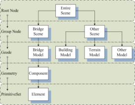
1) A scene hierarchy of the scene model is necessary for solving rendering efficiency problems. The bridge scene model presented in this paper has good performance in improving the rendering efficiency and realistic effect.

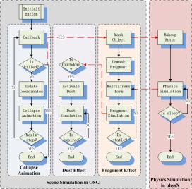
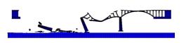
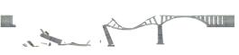
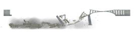
2) Utilization of the Callback method of OSG to perform collapse animation is very suitable to the simulation process. The scene simulation presented in this paper is as accurate as the FE simulation, but it is more realistic and complete than the FE simulation.

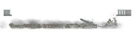
3) Management of killed FE elements, which are simulated as fragment effects, is a very important technology that solves the problem resulting from the shortage of information from the movement of killed FE elements.

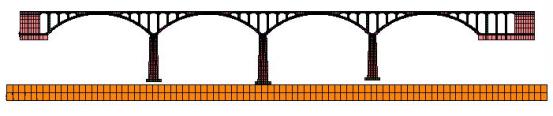
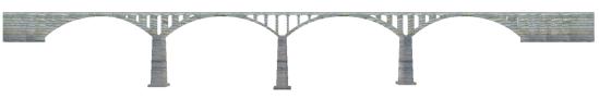
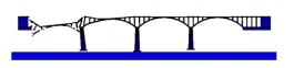
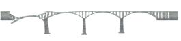
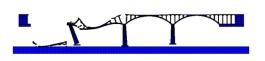
4) The bridge collapse scene simulation is convenient for the observation of the process of collapse, and it provides an important reference for the analysis of bridge collapse accidents.

Acknowledgements

The research presented in this paper was funded by the Scientific and Technical Projects of Transportation Construction in Western by the Ministry of Transport of China (No. 2008-318-223-43), Major S&T Special Project of Ministry of Transport of PR China (No. 2011-318-223-170) and Tsinghua University Research Funds (No. 2011THZ03). The authors are sincerely thankful for this support.

References

CHEN J.T., XIAO M., ZHENG Y.L.,2006. Development of 3D graphics system of finite elements for underground engineering using OpenGL. Chinese Journal of Rock Mechanics and Engineering, 25(5):1015-1020. ( In Chinese)

FRITZ K. and ANDREAS M. S., 2004. Virtual process engineering - an approach to integrate VR, FEM, and simulation tools in the manufacturing chain, Machine and Industry, 5(2): 199-205.

HAO S., 2010. I-35W Bridge Collapse, Journal of Bridge Engineering, 15(5):608-614.

ISOBE D., TSUDA M., 2003. Seismic collapse analysis of reinforced concrete framed structures using the finite element method, Earthquake Engineering and Structural Dynamics, 32(13):2027-2046.

KUMAR P. and BHANDARI N. M.,2005. Non-linear finite element analysis of masonry arches for prediction of collapse load, Structural Engineering International, 15(3): 166-175.

LU XZ., YE LP., MA YH., TANG DY., 2012. Lessons from the collapse of typical RC frames in Xuankou School during the great Wenchuan Earthquake, Advances in Structural Engineering, 15(1): 139-153..

MORTEN B. and STEPHANE C., 2003. Real-time volumetric deformable models for surgery simulation using finite elements and condensation, Computer graphics forum, 15(3): 57 -66.

NIKITIN I., NIKITINA L., FROLOV P., et al, 2002. Real-time simulation of elastic objects in virtual environments using finite element method and precomputed Green's functions. In: EGVE '02 Proceedings of the workshop on Virtual environments 2002, 2002, Switzerland.

NVIDIA CORPOTATION, 2008. Physics SDK API Reference, Available online: http://www.nvidia.com/, Last accessed: August 2010.

XIAO P., LIU G.D. and XU M.L.,2010. Programming Guide of OpenSceneGraph 3D Graphic Engine, Beijing: Tsinghua University Press. ( In Chinese)

XU Z., LU X.Z., GUAN H., LU X., REN A.Z., 2011. Progressive-collapse simulation and critical region identification of a stone arch bridge, Journal of Performance of Constructed Facilities, in press, doi:10.1061/(ASCE)CF.1943-5509.0000329.

YU W. and WU W.Y., 2001. 3D Visualization and simulation technique and reconstruction of a disaster. Chinese Journal of Stereology and Image Analysis, 6(2):122-127. ( In Chinese)

WANG R. and QIAN X.D., 2009. Design and Practice in OpenSceneGraph 3D Graphic Engine, Beijing: Tsinghua University Press. ( In Chinese)

Introduction
Research
Application
Teaching
Publications
Download
Issues
Others


Our Lab

Collapse Prevention Committee