Progressive collapse resistance demand of RC frames under catenary mechanism

Yi Li, Xinzheng Lu, Hong Guan, and Lieping Ye

ACI Structural Journal, 2014, 111 (5), 1225-1234.

Download Full Text  

ABSTRACT

Progressive collapses are resisted by the catenary mechanism in RC frame structures undergoing large deformations. Research to date has mainly focused on the nonlinear dynamic progressive collapse resistance demand of this type of structures under the beam mechanism (i.e., for small deformations), and that for the catenary mechanism is lacking. As a first attempt, this study establishes a dynamic amplification factor for evaluating the resistance demands of RC frames under the catenary mechanism. To achieve this, an energy-based theoretical framework is proposed for calculating the aforementioned demands. Based on this framework, the analytical solution for collapse resistance demands of regular RC frames under the catenary mechanism is readily obtained. Numerical validation indicates that the proposed equations can accurately describe the progressive collapse demand of RC frames undergoing large deformations.

Keyword£ºRC frame, progressive collapse, catenary mechanism, resistance demand, energy conservation principle

If you need the PDF version of this paper, please email to luxinzheng@sina.com

RESEARCH SIGNIFICANCE

This study for the first time investigates the dynamic amplification factor (DAF) for RC frames under catenary mechanism. The method proposed is useful for effective assessment of the progressive collapse resistance demand of RC frames undergoing large deformations which is a simpler alternative to the direct nonlinear dynamic approach. Unlike existing work, the proposed demand relationship, i.e. DAF, is classified into a structural DAF and an elemental DAF, which can be evaluated using an energy-based theoretical framework developed in this study. This framework will facilitate further studies on the nonlinear dynamic effect of other types of structural systems.

INTRODUCTION

Progressive collapse of building structures is defined as a local damage caused by an accidental event propagating throughout the entire structural systems1. In the past few decades, the progressive collapse events triggered by gas explosions, bombing attack, fire and vehicular collisions, have been continuously reported. Extensive research has been conducted to investigate and improve progressive collapse resistance of building structures.

Existing experimental2-5 and numerical6-8 investigations have demonstrated that progressive collapses of reinforced concrete (RC) frame structures are resisted by end moments of the beams for small deformations (namely, the beam mechanism), and by axial tensile forces in the beams for large deformations (namely, the catenary mechanism). The latter is a one-way load-transfer mechanism where the external load is resisted by the beams in one direction. When the frame structures undergo large deformations, cast-in-situ RC floor slabs exhibit a two-way membrane tension effect9 in which the load transfer in each direction is equivalent to a catenary mechanism. The catenary mechanism is the prototype model of the tie force (TF) method adopted in the design codes10-12, by which the axial force demand of beams (in one direction) and floor slabs (in two directions) is calculated. Progressive collapses of an RC frame structure can be effectively prevented through catenary action which enhances the structural integrity after a part of the structure has become a mechanism. Note in the existing TF method that only the nonlinear static (NS) demand under the catenary mechanism is considered. The dynamic effect of the actual progressive collapse process is however neglected, and this may lead to an unsafe design13.

The nonlinear dynamic (ND) demand is a more realistic representation of the progressive collapse resistance demand, which can be calculated using dynamic equilibrium equations or energy conservation equations. However, to solve dynamic equilibrium equations, nonlinear dynamic finite element analysis is commonly performed, which is time-consuming. Hence, dynamic analyses are generally used for buildings with high security risks10-11. To solve energy conservation equations based on the conventional methods14-16, both energy dissipation and work done by the unbalanced gravity load must be calculated for every single structural member, which is also a tedious task for engineering design.

In view of the above, more engineer-friendly methods, such as linear static or nonlinear static (NS) methods, have been widely adopted in the existing progressive collapse design code10. This is followed by the correction of the above NS demand to conveniently approximate the ND demand using a dynamic amplification factor (DAF). Based on this concept, the progressive collapse resistance demand under the beam mechanism has been studied in the past, using the dynamic method17 and the energy method18-20. However, little research has been devoted to the demand evaluation under the catenary mechanism for RC frame structures.

In addition to the aforementioned research gap, another critical problem associated with the existing energy-based approaches is the energy distribution in different structural components18-20. In these approaches, the single-degree-of-freedom (SDOF) model is widely adopted to represent the mechanical characteristics, including collapse resistance and deformation, of the collapse-resisting substructures, as shown in Figure 1. It should be noted that the resistance of the SDOF model refers to as the collapse-resisting capacity of the overall structure, namely the structural resistance. Note also that the structural resistance is provided by the structural elements in the substructure but is not a simple summation of their individual elemental resistance due to complicated load-redistribution characteristics in the structural system. Accordingly, the DAF for the structural resistance is different from that for the elemental resistance. The DAF 18-20 for the beam mechanism obtained based on the SDOF model is the structural-level DAF, i.e., DAFs. However in engineering designs the elemental-level DAF, i.e., DAFe, is required to determine the resistance demand of the structural elements. Further, the relationships between the DAFs and the DAFe describe the distribution of the total energy dissipation in resisting progressive collapse throughout the structural system. However, the values of DAFs and DAFe have not been identified in the existing studies and more specifically the elemental-level DAFe has not yet been studied before.

This paper thus aims to present an energy-based theoretical framework for calculating the structural and elemental demand relationships between the NS and ND demands of RC frame structures under the catenary mechanism. Based on this framework, the DAFs and DAFe are derived for regular RC frames undergoing large deformations. The two DAFs are validated through a series of numerical examples with varying parameters.

FUNDAMENTAL CONCEPTS

The abovementioned resistance demands can be classified by the analysis targets (i.e., structural or elemental demand) and the analysis techniques (i.e., NS or ND method) as shown in Table 1, which are briefly defined as follows.

Structural and elemental demands

For RC frame structures under the catenary mechanism, the collapse resistance demands include the structural demand Rc of the substructures and the elemental demand F of the beam members.

NS and ND demands

The progressive collapse resistance demands under the catenary mechanism can be calculated using the NS or ND method. The corresponding outcomes of these methods are, respectively, referred to as the NS and ND demands.

Detailing requirement

Under large deformations, the catenary mechanism of a RC frame is substantiated by the detailing requirement in order to provide effective axial forces through the beams. For example, reinforcing steel bars designed to provide the progressive collapse resistance demand are required to be continuous along the entire length of the beam and be effectively embedded or anchored10. Note that this study focuses on the progressive collapse resistance demand under the catenary mechanism. Therefore RC frame structures with adequate ductility and continuous reinforcement arrangement are considered.

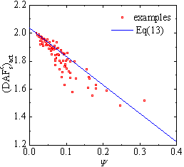
THEORETICAL FRAMEWORK FOR DEMAND ANALYSIS

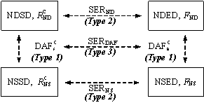
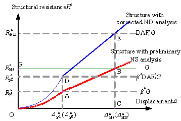
The demand relationships can be categorized into three types (see Figure 2a): Type 1, the relationship between the ND and the NS demands. In this study, these demand relationships at the structural and elemental levels for the catenary mechanism are designated as DAFc s and DAFc e, respectively. Type 2, the relationship between the structural and elemental demands, which can be described by the structural-to-elemental demand ratio (SER). In this study, SERNS and SERND are used to describe the NS and ND structural-to-elemental demand ratios, respectively. Type 3, the relationship between the DAFc s and DAFc e, which is referred to as the SERDAF.

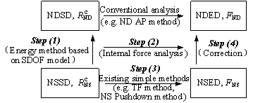
Figure 2b presents the proposed theoretical framework of the energy-based progressive collapse demand analysis which includes the following four major steps:

Step (1): take the progressive collapse-resisting substructures as the study object (idealized as a SDOF system, see Figure 1) and establish the expression of the DAFc s based on the energy conservation principle.

Step (2): analyze the mechanical mode of substructures under the catenary mechanism and establish the SERDAF, based on which DAFc s can be converted into DAFc e.

Step (3): determine the NSED using the NS analysis.

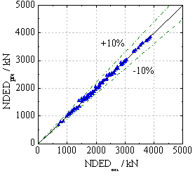
Step (4): correct the NSED to approximate the NDED using the DAFc e obtained in Step (2).

The framework shown in Figure 2b provides a feasible energy-based method of calculating the DAFc e in which the calculation of the energy dissipation of every member in the substructure is not required.

RESISTANCE CURVE FOR RC FRAMES UNDER THE CATENARY MECHANISM

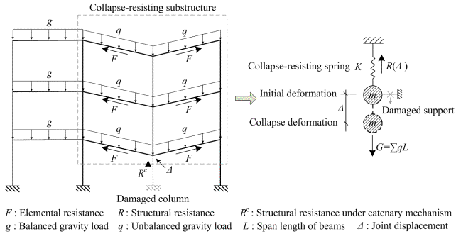
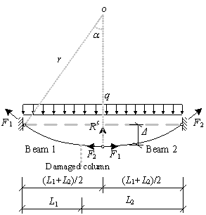
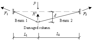
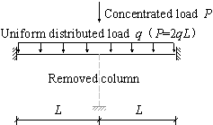
For the regular substructure shown in Figure 1, when the progressive collapse resistance demands of the beams are satisfied at every storey, the demands of the substructures are also satisfied. In this study, the two framed beams are isolated from the substructure to evaluate the demands of the beam elements under the catenary mechanism. This is presented in Figure 3. A progressive collapse in the framed beams can be resisted by the structural resistance Rc and the elemental resistance, i.e., the axial tensile forces (F1 and F2) in the beams. The framed beams may deform into two different shapes, depending on the type of load and the horizontal stiffness of the support constraints. Under a uniformly distributed load q, the beams deform into a curve-type catenary, as shown in Figure 3a. This is the calculation model for the code specified TF method10-12, as described in Appendix B of UFC21. On the other hand, when subjected to a concentrated load P, the beams deform into a straight-type catenary, as shown in Figure 3b. The latter has been observed in the published laboratory test results2-5. In practice, when the disproportionate collapse occurs in the intermediate floors of a multi-story building due to the local failure of a vertical element, a large concentrated load from the upper story columns is expected on top of the missing element. This results in a straight type catenary mechanism. For the top floor, on the other hand, the existence of the uniformly distributed load would lead to a curve type catenary mechanism.

Curve-type catenary mechanism

For the two beams shown in Figure 3a, the maximum vertical displacement D occurs at the mid-span, i.e., (L1+L2)/2, of the two beams. For both small and large deformations, Rc, F1 and F2 at the location of maximum deformation must satisfy the following equations, which is obtained through moment equilibrium of the left or the right symmetrical freebody with respect to the support point:


(1a)


(1b)

For RC beams, the axial forces are provided by the longitudinal reinforcing bars embedded in the beams. Before yielding of the steel bars, the beam ends undergo primarily the plastic hinge rotations, with a small amount of axial deformation. At this stage, the axial force F1 can be calculated from the following equation according to the deformation mode of the beams.


(2)

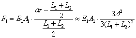
where E1 and A1 are the modulus of elasticity and the cross-sectional area of the longitudinal reinforcing bars, respectively. As shown in Figure 3a, r is the radius of the catenary arc and a is the subtended angle of the half arc. Note that a can be expressed as arcsin[(L1+L2)/2r] and the first two terms of the Taylor¡¯s polynomials of a is given in Eq.(2).

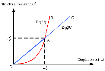
Substituting Eq. (2) into Eq. (1) gives the structural resistance under the catenary mechanism Rc L before the beams yield in tension.


(3a)

Corresponding to the expression in Eq. (3a), the curve OAB in Figure 4 represents the behavior of the catenary action before the beams yield.

After yielding of the longitudinal reinforcing bars in the beams, assuming that Beam 1 has relatively smaller tensile yield strength than Beam 2 has, the axial force F1 remains the same as the yield force F1y of Beam 1. Based on Eq. (1), the structural resistance under the catenary mechanism Rc N after yielding of the beams becomes the following:


(3b)

The expression in Eq. (3b) refers to the straight line OC in Figure 4, which represents the catenary action following tension yielding in the beams.

Straight-type catenary mechanism

According to the straight-type catenary mechanism shown in Figure 3b, Rc, F1 and F2 satisfy the following equations:


(4a)


 when D¡Ü0.2¡Ámin(L1,L2)

(4b)

Note that the discrepancy in the axial forces in two beams is less than 2% if the beam length ratio becomes as large as 10, which is rarely practical.

Similar derivations as presented above are adopted herein. Under the straight-type catenary mechanism, the structural resistances Rc L and Rc N before and after yielding of the longitudinal reinforcing bars are given by Eqs 5(a) and 5(b), respectively:


(5a)


(5b)

Eqs. 5(a) and 5(b) indicate that RC frames under the straight-type catenary mechanism exhibit similar mechanical behavior, as illustrated in Figure 4.

Effect of beam mechanism

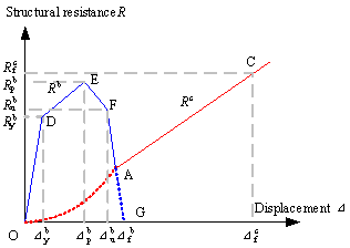
It is well accepted that RC framed beams behave in the form of a beam mechanism before exhibiting the catenary mechanism2-8. Therefore, as Figure 5 shows, the entire resistance curve of an RC frame structure is defined by the polyline ODEFA under the beam mechanism and the straight line AC under the catenary mechanism. The polyline connects such key points as the reference point O (0, 0), the yield point D (Db y, Rb y), the peak point E (Db p, Rb p), the ultimate point F (Db u, Rb u) and the failure point G (Db u, 0) of the resistance curve of the RC frame structures under the beam mechanism13. In the figure, Dc f and Rc f are the ultimate displacement and the ultimate structural resistance, respectively, of an RC frame under the catenary mechanism. In this paper, the structural and elemental resistance demands of the RC frames exhibiting the catenary mechanism are studied first. This is followed by further analysis of the effect of the beam mechanism on the demands under the catenary mechanism.

STRUCTURAL DEMAND RELATIONSHIP OF RC FRAMES UNDER CATENARY MECHANISM

The analytical expression of the DAFs under the curve-type catenary mechanism, DAFc s, is derived in this section. The DAFc s under the straight-type mechanism will be discussed at the end of the section. The NSSD and NDSD are notionally illustrated in Figure 6. The NSSD, Rc NS, is represented by Point B, which satisfies the static equilibrium condition under the unbalanced gravity load G and can be evaluated by the preliminary NS analysis. The NDSD, Rc ND, is represented by Point E, which satisfies an additional demand induced by the nonlinear and dynamic effects during the collapse process, and it can be determined by correcting the analysis through the DAFc s.

In the existing codes of practice10-12, the ultimate displacement Dc f of the RC framed beams under the catenary mechanism is specified as 0.2L, where L is the span length of the beams. Therefore, the ND and NS displacements, Dc ND and Dc NS, are identical, as shown in Figure 6. To simplify the theoretical discussion, it is assumed that the yield displacements Dc y1 and Dc y2, corresponding to the yield resistances Rc y1 and Rc y2, respectively, are equal, as indicated in Figure 6. Note that the energy dissipated before reaching Dc y1 and Dc y2 only consumes a very small proportion of the total energy. For example, the framed beams discussed later in Figure 7 only dissipate 3.32% of the total energy before reaching Dc y1 or Dc y2. Therefore, under the above assumption, slight discrepancies are expected in the solution.

In accordance with the energy conservation condition in which the work done by the unbalanced gravity load (i.e., the area OFBC) is equal to the energy dissipation by the structure (i.e., the area ODEC), the energy equation of the RC frames under the curve-type catenary mechanism is as follows:


(6)

where AND is the cross-sectional area of the longitudinal reinforcing bars in the framed beams for the ND demand. For Rc y2 and Dc y to satisfy Eq. (3a), we have the following:


(7)

The yield factor ¦Âc of the substructures is defined as:


(8a)

Considering the above discussion on Dc ND, Dc NS, Dc y1 and Dc y2, Eq. (3b) and Eq. (8a) produce the following:


(8b)

and


(9)

Substituting Eqs. (7¨C9) into Eq. (6) yields the NDSD, Rc ND, under the curve-type catenary mechanism.


(10)

Considering the DAFc s as defined above and Eq. (10), the structural demand relationship DAFc s of an RC frame structure under the curve-type catenary mechanism can be expressed as follows:


(11)

It should be noted that the initial energy can be dissipated by the beam mechanism. Thus, the resistance demand under the catenary mechanism is decreased. Assuming that the energy dissipation Ub by the beam mechanism is as follows:


(12)

where  is the energy dissipation factor representing the ratio of the partial (by the beam mechanism) to the total energy dissipations, we then have the DAFc s, considering the energy dissipation of the beam mechanism, as follows:


(13)

Eq. (13) describes the relationship between NDSD and NSSD of an RC frame structure under the curve-type catenary mechanism.

The expressions for DAFc s for the straight-type catenary mechanism can be derived following the same procedure as described above, except that the expressions associated with the straight-type catenary mechanism should be adopted in Eq. (6) and Eq. (7). This indicates that the relationships between the ND and NS demands for the two mechanisms are identical.

RELATIONSHIP BETWEEN STRUCTURAL AND ELEMENTAL DEMANDS OF RC FRAME STRUCTURES UNDER CATENARY MECHANISM

According to Eq. (3b), the relationships between NSED, (F1y)NS, and NSSD, Rc NS, and those between NDED, (F1y)ND, and NSSD, Rc ND, satisfy Eqs. (14a) and (14b), respectively:


(14a)


(14b)

Thus, the relationship between DAFc e and DAFc s, i.e., SERDAF, satisfies Eq. (15):


(15)

For the straight-type catenary mechanism, an identical relationship between DAFc e and DAFc s can be established following the process outlined above.

Note that the above theoretical derivations for the DAFc e and DAFc s are based on the regular RC frame structures shown in Figures 1 and 3. The derived Eq. (15) indicates that the structural DAF equals the elemental DAF for a regular RC frame under the catenary mechanism.

Eq. (15) can be transformed into the following equation:


(16)

The physical significance of Eq. (16) is that, for regular RC frame structures, the distributions of the total static demand and the total energy dissipation demand of all the structural elements in the collapse-resisting substructure are identical. It should be noted, however, for the irregular frame structures defined in GSA200322, that the characteristics of the DAFc e, DAFc s, SERNS and SERND do not necessarily follow the above observation and that they must be evaluated case by case using the proposed methodology.

NUMERICAL VALIDATION

Validation method

The numerical validation is performed using the nonlinear finite element program THUFIBER13. Published literatures confirm that RC frames exhibiting a flexural and axial behavior can be well simulated using THUFIBER13,23. The independent NS and ND analyses are conducted to obtain the NS and ND demands, respectively. Figure 7a shows a theoretical model of one-story two-span continuous framed beams used to validate the proposed demand relationships. Details of the model are given in the next section, and the validation procedure is summarized below in five stages.

Stage (1): Calculate the actual NSED and NSSD.

An NS pushdown analysis is conducted herein. The amount of longitudinal reinforcing steel is iteratively adjusted until the pushdown load equals the unbalanced gravity load G when the joint displacement reaches the target displacement, i.e., 0.2L10-12. The resulting frame satisfies the NS demand, i.e. the static equilibrium condition under the unbalanced gravity load G. The corresponding axial force in the beams is therefore taken as the actual NSED, (F1y)NS. Note that the actual NSSD equals the gravity load G.

Stage (2): Calculate the actual NDED and DAFc e

For the framed beams established in Stage (1), a gravity load G is initially considered to be applied to the beams, and a static analysis is conducted until the static equilibrium state is reached. This state corresponds to 1s in Figure 7b, which is followed by a sudden removal of the middle support. A transient ND analysis is subsequently conducted to simulate the dynamic response of the framed beams, as shown in Figure 7b. During the ND analysis, the amount of longitudinal reinforcing steel is iteratively adjusted until the catenary mechanism takes place and the corresponding displacement reaches the target displacement specified in the existing codes, i.e., 0.2L10-12. The resulting frame satisfies the ND demand, i.e. the energy equilibrium condition under the unbalanced gravity load G. The corresponding maximum axial force in the beams is recorded as the actual NDED, (F1y)ND. Thus, the actual value of DAFc e can be expressed as follows:


(17)

Stage (3): Calculate the actual NDSD and DAFc s

An NS pushdown analysis is conducted again for the framed beams obtained in Stage (2), satisfying the ND demand, to calculate the actual NDSD, as shown in Figure 7c. The target displacement, 0.2L, and the load pattern in the pushdown analysis are identical to those in the transient ND analysis (Stage (2)). The pushdown load at the target displacement 0.2L is taken as the actual NDSD, i.e., Rc ND. Thus, the actual value of DAFc s, i.e., (DAFc s)act, is given by the following:


(18)

Stage (4): Calculate and validate the predicted DAFc sand compare the structural and elemental DAFs

For the numerical model being analyzed, the actual structural DAF, (DAFc s)act obtained in Stage (3) is compared with the predicted DAF, (DAFc s)pre. Note that (DAFc s)pre is calculated using Eq. (13), in which the energy dissipation factor Y under the beam mechanism is determined by the ratio of the area below ODEFA to that below ODEFAC of the pushdown curve calculated in Stage (2), as illustrated in Figure 7c. The yield factor ¦Âc in Eq. (13) is given by Eq. (8), in which the yield displacement Dc y of the catenary mechanism is determined by the transformation point from the beam mechanism to the catenary mechanism (i.e., Point A in Figure 7c). The actual structural and elemental DAFs, i.e., (DAFc s)act and (DAFc e)act, are also compared in the following section to validate Eq. (15) which describes their theoretical relationship.

Stage (5): Calculate the predicted NDED and validate the proposed energy-based framework

Based on the proposed framework outlined in Figure 2b, the predicted NDED, NDEDpre, is calculated by correcting the actual NSED obtained in Stage (1) using the predicted (DAFc s)pre obtained in Stage (4). Subsequently, the NDEDpre is compared with the actual NDED, NDEDact, obtained by the direct ND analysis conducted in Stage (2).

Model parameters

To ensure the representativeness of the validation, different parameters, including the load type and magnitude, the span length and the cross-sectional dimension of the beams, are considered, as summarized in Table 2. This results in 180 models in total. A uniformly distributed load and a concentrated load are applied to investigate the resistance demand under the curve- and straight-type catenary mechanisms, respectively.

To investigate the effect of the beam mechanism, two different reinforcing scenarios are considered, as shown in Figure 8. In the first scenario, the structure is reinforced with two steel bars with diameters of 22 mm (0.866in) at the top of the beam ends. This corresponds to a 0.22% to 0.33% reinforcement ratio, which is greater than the minimum ratio of 0.2% specified in the Chinese Design Code of Concrete Structures24. This minimum ratio is widely adopted in frames designed without consideration for seismic effects. In the second scenario, the structure is reinforced with six steel bars with diameters of 22 mm (0.866in) at the top of the beam ends, which corresponds to a 1.3% to 2.1% reinforcement ratio. This ratio is smaller than the code-specified maximum ratio of 2.5%25 and is commonly used in frames designed with consideration for seismic effects. The above two scenarios cover the upper and lower limits of the energy dissipation effects of the beam mechanism. For all the models, two additional bars with diameters of 22 mm (0.866in) are also placed at the top sections at the mid-span of the beams. The bottom bars are positioned along the entire length of the beams. The cross-sectional areas of the bottom bars are iteratively adjusted until the target displacement of 0.2L is reached for the catenary mechanism.

Validation results

The validation for the structural demand relationship, DAFc s, is illustrated in Figure 9. It is evident that the predicted values of (DAFc s)pre are very close to the actual values of (DAFc s)act, with the majority of the errors within ¡À10% and the mean absolute percentage errors are 2.61% and 2.44% for the curve-type and straight-type catenary mechanisms, respectively. This indicates that the proposed Eq. (13) is able to accurately predict the relationship of the structural resistance demands of RC frame structures under the catenary mechanism. It is also observed that the DAFc s under the catenary mechanism ranges from approximately 1.5 to 2.0. This value is larger than the DAFb s under the beam mechanism, which is below 1.34 for regular RC frame structures with a ductility ratio greater than 1.0 in the NS analysis10.

In the existing design codes, the NS elemental demand is directly adopted for the TF design. The validation results reveal that the actual ND elemental demand is approximately 1.5 to 2.0 times the NS elemental demand. This indicates that the demand calculated by the existing TF method is insufficient for collapse prevention, therefore the method should be further modified to ensure safe design for the catenary mechanism. It is also noticed that only the DAF for the beam mechanism is regulated in the existing design codes which is much lower than that for the catenary mechanism. If the currently recommended DAF is used to correct the demand under the catenary mechanism, the solution would be underestimated. To improve the demand calculation method for the catenary mechanism, the proposed equations: Eq. (13) and Eq. (15), can be used to correct the NS demand in the existing TF design.

The effect of the beam mechanism on the structural demand under the catenary mechanism is illustrated in Figure 10. The square dots denote the relationship between the energy dissipation factor Y and (DAFc s)act for all 180 numerical models. Substituting the average value of ¦Âc of the validation models into Eq. (13) gives the nominal average value of (DAFc s)act as a function of Y, which is represented by the solid line in Figure 10. It is apparent that when the energy dissipation by the beam mechanism increases, the structural demand under the catenary mechanism decreases. It is well known that the beams in RC frame structures constructed in earthquake zones are designed to have higher bending moment capacities than those constructed in non-earthquake zones. As a result, RC frame structures with seismic design considerations have higher energy dissipating capacities under the beam mechanism in a progressive collapse process. Consequently, the collapse resistance demand of these structures under the catenary mechanism decreases.

In Figure 11, the actual values of the elemental (DAFc e)act are compared to those of the structural (DAFc s)act for all 180 models. Again, the mean ratios of (DAFc e)act and (DAFc s)act are well within ¡À10% and the mean absolute percentage errors are 2.49% and 2.64% for the curve-type and straight-type catenary mechanisms respectively. This further validates the proposed relationship (Eq. (15)) under the catenary mechanism.

The NDED predicted by the proposed energy-based framework (Figure 2b) is validated by comparing with the actual value of NDED, as presented in Figure 12. A ¡À10% band of scatter envelopes the majority of the 180 data points. The mean absolute percentage errors are 3.39% and 1.79% for the curve-type and straight-type catenary mechanisms, respectively. This further demonstrates that the NDED of the numerical examples can be well assessed by the proposed framework.

CONCLUSIONS

Under large deformations, RC frame structures resist progressive collapse through the catenary mechanism. An energy-based framework is proposed for calculating the progressive collapse resistance demands under the catenary mechanism at both the structural and elemental levels. The following conclusions can be drawn.

1. Two types of catenary mechanisms, viz. the curve type and the straight type are similar mechanisms and are identical in their DAF values.

2. For regular RC frame structures, the elemental DAF equals the structural DAF. These two values may not be identical for irregular frame structures with varied structural arrangement from story to story. This aspect merits further investigation.

3. For structures with seismic design considerations, the beam mechanism capacity increases, which subsequently reduces the catenary mechanism demand, due to the noticeable contribution of the energy dissipation of the beam mechanism.

4. Numerical validation using a total of 180 framed beam models demonstrates that the proposed relationships are accurate and that the DAFc s under the catenary mechanism is larger than the DAFb s under the beam mechanism. The proposed DAFc e can be used to correct the NS elemental demand in order to approximate the ND elemental demand.

ACKNOWLEDGEMENT

The authors are grateful for the financial support received from the National Basic Research Program of China (No. 2012CB719703), the National Science Foundation of China (No. 51222804, 51208011), Program for New Century Excellent Talents in University (NCET-10-0528), and Research Program of Beijing Municipal Commission of Education (KM201310005025).

REFERENCES

1.  Ellingwood, B.R., ¡°Mitigating risk from abnormal loads and progressive collapse,¡± J Perf Constr Fac, ASCE, V.20, No.4, Nov., 2006, pp.315-23.

2. Yi, W.J., He, Q.F., Xiao, Y., and Kunnath, S.K., ¡°Experimental Study on Progressive Collapse-Resistant Behavior of Reinforced Concrete Frame Structures,¡± ACI Structural Journal, V.105, No.4, Jul.-Aug., 2008, pp.433-439.

3. Su, Y., Tian, Y., and Song, X., ¡°Progressive Collapse Resistance of Axially-Restrained Frame Beams,¡± ACI Structural Journal, V.106, No.5, Sep.-Oct., 2009, pp.600-607.

4. Sadek, F., Main, J.A., Lew, H.S., and Bao, Y., ¡°Testing and Analysis of Steel and Concrete Beam-Column Assemblies under a Column Removal Scenario,¡± Journal of Structural Engineering, ASCE, V.137, No.9, Sep., 2011, pp.881-892.

5. Yu, J., and Tan, K., ¡°Experimental and Numerical Investigation on Progressive Collapse Resistance of Reinforced Concrete Beam Column Sub-Assemblages,¡± Engineering Structures, Available online 15 Dec, 2011 (In Press)

6. Sasani, M., Wernera, A., and Kazemia, A., ¡°Bar Fracture Modeling in Progressive Collapse Analysis Of Reinforced Concrete Structures,¡± Engineering Structures, V.33, No.2, Feb., 2011, pp.401-409.

7. Bao, Y., Kunnath, S.K., El-Tawil, S., and Lew, H.S., ¡°Macromodel-Based Simulation of Progressive Collapse: RC Frame Structures,¡± Journal of Structural Engineering, ASCE, V.134, No.7, Jul., 2008, pp.1079-1091.

8. Valipour, H.R., and Foster, S.J., ¡°Finite Element Modelling of Reinforced Concrete Framed Structures including Catenary Action,¡± Computer & Strcutures, V.88, No.9-10, May., 2010, pp.528-538.

9. Mansur, M.A., Ahmad, I., and Paramasivam, P., ¡°Punching Shear Strength of Simply Supported Ferrocement Slabs,¡± Journal of Materials in Civil Engineering,ASCE, V.13, No.6, Nov.-Dec., 2001, pp.418-426.

10. Department of Defense (DoD). ¡°Unified Facilities Criteria (UFC): Design of Structures to Resist Progressive Collapse.¡± Department of Defense, UFC 4-023-03, U.S. Army Corps of Engineers, Washington, DC, 2010, 181 pp.

11. European Committee for Standardization, ¡°EN 1992-1-1:2004, Eurocode 2: Design of Concrete Structures. Part 1: General Rules and Rules for Buildings,¡± Brussels, Belgium, 2004, 226 pp.

12. British Standard Institute, ¡°BS8110: Structural Use of Concrete, Part 1: Code of Practice for Design and Construction,¡± London, United Kingdom, 1997, 164 pp.

13. Li, Y., Lu, X.Z., Guan, H., and Ye, L.P., ¡°An Improved Tie Force Method for Progressive Collapse Resistance Design of Reinforced Concrete Frame Structures,¡± Engineering Structures, V.33, No.10, Oct., 2011, pp.2931-2942.

14. Dusenberry, D.O., and Hamburger, R.O., ¡°Practical Means for Energy-Based Analyses of Disproportionate Collapse Potential,¡± Journal of Performance of Constructed Facilities, ASCE, V.20, No.4, Nov., 2006, pp. 336-348.

15. Izzuddin, B.A., Vlassis, A.G., Elghazouli, A.Y., and Nethercot, D.A., ¡°Progressive Collapse of Multi-Storey Buildings due to Sudden Column Loss-Part I: Simplified Assessment Framework,¡± Engineering Structures, V.30, No.5, May., 2008, pp. 1308-1318.

16. Xu, G., and Ellingwood, B.R., ¡°An Energy-Based Partial Pushdown Analysis Procedure for Assessment of Disproportionate Collapse Potential,¡± Journal of Constructional Steel Research, V.67, No.3, Mar., 2011, pp. 547-555.

17. Marchand, K.A., McKay, A.E., and Stevens, D.J., ¡°Development and Application of Linear and Non-Linear Static Approaches in UFC 4-023-03,¡± Proceedings of the 2009 Structures Congress. Austin, Texas, United States, 2009. pp. 1-10.

18. Pujol, S., and Smith-Pardo, J.P., ¡°A New Perspective on The Effects of Abrupt Column Removal,¡± Engineering Structures, V.31, No.4, Apr., 2009, pp. 869-874.

19. Tsai, M.H., and Lin, B.H., ¡°Investigation of Progressive Collapse Resistance and Inelastic Response for an Earthquake-Resistant RC Building Subjected to Column Failure,¡± Engineering Structures, V.30, No.12, Dec., 2008, pp. 3619-3628.

20. Tsai, M.H., ¡°An Analytical Methodology for the Dynamic Amplification Factor in Progressive Collapse Evaluation of Building Structures,¡± Mechanics Research Communications. V.37, No.1, Jan., 2010, pp. 61-66.

21. Department of Defense (DoD). ¡°Unified Facilities Criteria (UFC): Design of Structures to Resist Progressive Collapse.¡± Department of Defense, UFC 4-023-03, U.S. Army Corps of Engineers, Washington, DC, 2005, 176 pp.

22. United States General Services Administration (GSA). ¡°Progressive Collapse Analysis and Design Guidelines for New Federal Office Buildings and Major Modernization Projects,¡± Washington, DC, 2003, 119 pp.

23. Lu, X., Lu, X.Z., Guan, H., and Ye, L.P., ¡°Collapse Simulation of Reinforced Concrete High-Rise Building Induced by Extreme Earthquakes,¡± Earthquake Engineering & Structural Dynamics. V.42, No.5, Apr., 2013, pp. 705-723.

24 The Ministry of Construction of the People¡¯s Republic of China, ¡°Code for Design of Concrete Structures (GB50010-2002),¡± Publishing House of Building Industry in China, Beijing, China, 2002, 425pp.

25. The Ministry of Construction of the People¡¯s Republic of China. ¡°Code for Seismic Design of Buildings (GB50011-2001),¡± Publishing House of Building Industry in China, Beijing, China, 2001, 483pp.


Appendix

PROOF OF UNIVERSALITY OF THE DEMAND RELATIONSHIPS

The theoretical derivations presented in the above sections are based on the simplified model illustrated in Figure 3, with pre-defined beam dimensions and material parameters. When the geometric dimensions and material parameters of Beam 1 and Beam 2 vary independently, E, A, L, D and Fy in Eq. (1) to Eq.(5) would change accordingly, which would in turn lead to a variation of the ratios of the structural to elemental demand (SERNS and SERND) regulated by Eq.(14). It should be noted, however, that the parameters L, D and Fy are eliminated in the calculation process as evident in Eq.(15). This indicates that the geometric dimensions and material parameters have no influence on the DAFc s and DAFc e. The above discussion clearly demonstrates that the structural and elemental demand relationships derived from the substructure in Figure 3 are universal for all regular RC frame structures.

NOTATION

The following symbols are used in the paper:

DAF

dynamic amplification factor

DAFs, DAFe

structural DAF and elemental DAF

DAFc s, DAFc e

structural and elemental DAFs under catenary mechanism

(DAFc s)act, (DAFc s)pre

actual and predicted values of DAFc s

(DAFc e)act, (DAFc e)pre

actual and predicted values of DAFc e

SERNS, SERND , SERDAF

structural-to-elemental ratio for NS demand, ND demand and DAF

E1, A1

elastic modulus and cross-sectional area of longitudinal reinforcing bars

AND

cross-sectional area of longitudinal reinforcing bars for ND demand

L, L1, L2

span length of beam

r

radius of catenary arc

R

structural demand

Rb, Rc

structural demand under beam mechanism and catenary mechanism

Rc L, Rc N

Rc before and after beam yield in tension

Rc y1, Rc y2

Rc when beam yield in tension

Rc NS, Rc ND

nonlinear static and nonlinear dynamic Rc

F, F1, F2

elemental demand under catenary mechanism

F1y

yield force of Beam 1

FNS, (F1y)NS

nonlinear static elemental demand

FND, (F1y)ND

nonlinear dynamic elemental demand

g

balanced uniformly distributed gravity load

q

unbalanced uniformly distributed gravity load

qp

uniformly distributed Pushdown load

P

unbalanced concentrated gravity load

G

total unbalanced gravity load

a

subtended angle of the half arc

D

joint displacement

Dc NS, Dc ND

nonlinear static and dynamic joint displacements under catenary mechanism

Dc y, Dc y1, Dc y2

yield displacement of substructure under catenary mechanism

Dc f

failure displacement of substructure under catenary mechanism

D max

target displacement

¦Âc

yield factor under catenary mechanism

energy dissipation factor of beam mechanism


tables and figures

List of Tables

Table 1.                     Types of demands under the catenary mechanism

Table 2.                     Parameters of the validation examples

List of Figures

Figure 1.                   The RC frame structure under catenary mechanism 

Figure 2.                   Framework of progressive collapse resistance demand analysis

Figure 3.                   Schematic diagram of substructure under catenary mechanism

Figure 4.                   Resistance curve of RC frame structures under catenary mechanism

Figure 5.                   Entire resistance curve of RC frame structures

Figure 6.                   Resistance demands of RC frame structures under catenary mechanism

Figure 7.                   Schematic diagram of validation method for progressive collapse resistance demand under catenary mechanism

Figure 8.                   Arrangement of steel bars in the validation models

Figure 9.                   Comparison between the actual and predicted values of DAFc s

Figure 10.               Effect of beam mechanism on structural demand under catenary mechanism

Figure 11.               Comparison between actual values of DAFc e and DAFc s

Figure 12.               Comparison between the actual and predicted values of NDED


Table 1. Types of demands under the catenary mechanism

         Analysis targets

Analysis techniques       

Structural-level

Elemental-level

Nonlinear

Static

Nonlinear static structural demand (NSSD, Rc NS)

Nonlinear static elemental demand (NSED, F NS)

Dynamic

Nonlinear dynamic structural demand (NDSD, Rc ND)

Nonlinear dynamic elemental demand (NDED, F ND)


Table 2  Parameters of the validation examples

Load type

Uniformly distributed load q

Concentrated load P (=2qL)

Concrete

C30 (fck=20.1 MPa)

Longitudinal reinforcing steel

HRB335 (fy=335 MPa)

Longitudinal steel bars at top sections of beam ends

Two 22-mm bars

Six 22-mm bars

Area load q (kN.m-1)

22.5

31.5

40.5

Beam span length L (m)

6

8

10

Cross-sectional dimensions (mm¡Ámm)

400¡Á300

450¡Á300

500¡Á300

550¡Á300

600¡Á300

Note: 1MPa=0.145ksi, 1mm=0.0394in, 1 kN.m-1=0.0685kip.ft-1, 1m=3.281ft.


Fig.1 The RC frame structure under catenary mechanism

Fig.1 The RC frame structure under catenary mechanism


Fig.2 Framework of progressive collapse resistance demand analysis

Fig.2 Framework of progressive collapse resistance demand analysis

(a) Demand relationships

(b) Analysis procedure

Fig.2  Framework of progressive collapse resistance demand analysis


Fig.3 Schematic diagram of substructure under catenary mechanism

  Fig.3 Schematic diagram of substructure under catenary mechanism

(a) Curve-type catenary mechanism

(b) Straight-type catenary mechanism

Fig.3 Schematic diagram of substructure under catenary mechanism


Fig. 4 Resistance curve of RC frame structures under catenary mechanism

Fig. 4 Resistance curve of RC frame structures under catenary mechanism


Fig. 5 Entire resistance curve of RC frame structures

Fig. 5 Entire resistance curve of RC frame structures


Fig. 6 Resistance demands of RC frame structures under catenary mechanism

Fig. 6  Resistance demands of RC frame structures under catenary mechanism


  Fig. 7 Schematic diagram of validation method for progressive collapse resistance demand under catenary mechanism

(a) Framed beam example

Fig. 7 Schematic diagram of validation method for progressive collapse resistance demand under catenary mechanism

Fig. 7 Schematic diagram of validation method for progressive collapse resistance demand under catenary mechanism

(b) Transient ND analysis

(c) NS pushdown analysis

Fig. 7  Schematic diagram of validation method for progressive collapse resistance demand under catenary mechanism

(parameters of demonstrated example: q=31.5 kN/m, L=8 m, 600(H)¡Á300(W) mm, uniformly distributed load, no seismic design)

Note: 1 kN.m-1=0.0685kip.ft-1, 1m=3.281ft, 1mm=0.0394in, 1 kN=0.225kips.


Fig. 8 Arrangement of steel bars in the validation models

Fig. 8 Arrangement of steel bars in the validation models

Note: 1mm=0.0394in.


Fig. 9 Comparison between the actual and predicted values of DAFc s

Fig. 9 Comparison between the actual and predicted values of DAFc s

(a) Curve-type catenary mechanism

(b) Straight-type catenary mechanism

Fig. 9  Comparison between the actual and predicted values of DAFc s


Fig. 10 Effect of beam mechanism on structural demand under catenary mechanism

Fig. 10 Effect of beam mechanism on structural demand under catenary mechanism

(a) Curve-type catenary mechanism

(b) Straight-type catenary mechanism

Fig. 10  Effect of beam mechanism on structural demand under catenary mechanism


Fig. 11 Comparison between the actual values of DAFc e and DAFc s

Fig. 11 Comparison between the actual values of DAFc e and DAFc s

(a) Curve-type catenary mechanism

(b) Straight-type catenary mechanism

Fig. 11  Comparison between the actual values of DAFc e and DAFc s


Fig. 12 Comparison between the actual and predicted values of NDED

Fig. 12 Comparison between the actual and predicted values of NDED

(a) Curve-type catenary mechanism

(b) Straight-type catenary mechanism

Fig. 12  Comparison between the actual and predicted values of NDED

Introduction
Research
Application
Teaching
Publications
Download
Issues
Others


Our Lab

Collapse Prevention Committee