Experimental Study of a Novel Multi-Hazard Resistant Prefabricated Concrete Frame Structure

Kaiqi Lin a, Xinzheng Lu b,*, Yi Lic, Hong Guand

(a Beijing Engineering Research Center of Steel and Concrete Composite Structures, Tsinghua University, China.

b Key Laboratory of Civil Engineering Safety and Durability of Ministry of Education, Tsinghua University, China.

c Key Laboratory of Urban Security and Disaster Engineering of Ministry of Education, Beijing University of Technology, China.

d Griffith School of Engineering, Griffith University Gold Coast Campus, Queensland 4222, Australia.)

Soil Dynamics and Earthquake Engineering, 2018,

DOI:10.1016/j.soildyn.2018.04.011

Download Full Text PDF

Abstract: Reinforced concrete (RC) frames are one of the most commonly used structural systems worldwide. Earthquake actions and progressive collapse caused by accidental local damage are two critical hazards increasing collapse risks of multi-story RC frames. A significant difference is well recognized between the structural seismic design and progressive collapse design. Whilst the seismic design focuses on resisting the lateral forces due to earthquake, the progressive collapse design deals with resisting the unbalanced vertical load induced by a localized failure. Existing research has revealed that considering the two different designs individually for a structure may lead to an undesirable overall structural performance and unnecessary waste of construction materials. In this study, a novel Multi-Hazard Resistant, Prefabricated Concrete (MHRPC) frame system is proposed to satisfy the demands of both structural seismic and progressive collapse designs. Cyclic and progressive collapse tests are conducted to validate the performance of this newly proposed structural system. The mechanisms of the MHRPC frame system under both cyclic loads and a middle column removal scenario are analyzed based on the experimental results and numerical simulations using OpenSees. The results indicate that the proposed fame system exhibits such characteristics as large rotation, low damage, self-centering, and ease of repair. The system is also proven to be able to meet the multi-hazard design requirements of RC frames against both earthquake actions and progressive collapse.

Keywords: multi-hazard; prefabricated concrete frame; earthquake; progressive collapse; experimental study; resilient

1 Introduction

Multiple hazards, such as earthquake, wind, fire and progressive collapse triggered by accidental local failure, impose enormous technical challenges to building structures throughout their service lives. Constructing multi-hazard resistant structures has become one of the most-concerned research focuses worldwide. For commonly constructed multi-story reinforced concrete (RC) frames, a number of existing studies have revealed that earthquake actions and progressive collapse are the two critical hazards affecting their structural performance and safety [1-2]. Progressive collapse refers to as the disproportionate chain collapse action of a structure initiated by a small and localized failure which may be caused by fire, explosion or overloading [3]. Typical examples of structural progressive collapse can be found in many existing literature, such as the 1968 collapse of Ronan Point apartment [3], the 1995 explosion of the Murrah Federal Building in Oklahoma City [2] and the 2001 fire induced progressive collapse of World Trade Center [4]. Progressive collapse of buildings can cause substantial loss of life and property, thereby leading to significant social, psychological and economic consequences.

According to the findings of the recent literature, a design method targeting for one particular hazard often unfavorably affects the structural performance against other hazards [5-6]. For example, Li & Sasani [7] and Livingston et al. [8] compared the progressive collapse resistance of frame beams in an ordinary frame and a special frame designed according to ACI 318-11 [9]. They discovered that the special frame is more ductile in terms of the structural seismic performance. On the other hand, the ordinary frame demonstrated a higher progressive collapse resistance under a column removal scenario. Lin et al. [10] discussed the interactions between seismic and progressive collapse designs using a vulnerability-based evaluation method. Their results indicated that using the current progressive collapse design method would result in an unfavorable ¡°strong beam-weak column¡± failure mode in RC frames, caused by the increased reinforcement ratios in the frame beams. This implies that the structural seismic performance might be weakened after implementing the current progressive collapse design separately. Note that in the current provision of the progressive collapse design guidelines [11-13], the requirement for the seismic performance re-evaluation or re-design after performing the progressive collapse design is still absent. As a result, the conventional single-hazard oriented design methods cannot satisfy the performance requirements of the seismic and progressive collapse designs simultaneously. It is therefore urgently needed to propose a comprehensive multi-hazard design solution for RC frames considering both seismic actions and progressive collapse.

In recent years, an increasing attention has also been paid to develop earthquake resilient structures. To date, seismic resilient RC structures are designed primarily by incorporating high performance components (i.e., prestressed tendons, energy dissipating devices and replaceable structural members) to control the damage distribution, residual deformation and to improve the structural post-earthquake reparability [14-18]. Specifically, in order to improve the seismic performance and resilience of RC structures, Wolski et al. [15] and Song et al. [16] tested the energy dissipating and self-centering capacities of a series of RC beam-column joints with post-tensioning (PT) tendons and energy dissipating devices. Their experimental results indicated that such frame joints underwent small residual deformations and displayed minor damage under a seismic action. Lu et al. [17] conducted a shaking table test of a half-scale two-story self-centering RC frame which further validated the seismic performance of such a structural system. Despite these considerable efforts, researchers have mainly focused on evaluating the seismic performance of such high-performance structures either on the system or component level. Limited studies have been reported on the evaluation of progressive collapse resistance of this type of structures.

In this study, a novel multi-hazard resistant prefabricated concrete frame (i.e., MHRPC frame) system, incorporating PT tendons, energy dissipating steel angles and shear plates, is proposed to meet the demands of both seismic and progressive collapse designs. Such a MHRPC frame system also takes great advantage of prefabricated structures. The use of steel angles, steel plates and jackets facilitate easily bolted connections between the beams and columns, without resorting to the traditional onsite welding. All the components can be prefabricated in the factory, accelerating the construction speed and improving the quality and safety of the structures.

Cyclic and progressive collapse tests are conducted to evaluate the multi-hazard resistant performance of this newly proposed frame system. Three design schemes are considered, i.e., a conventional RC frame (RC6), an RC frame after implementing the progressive collapse design (RD1) and a newly proposed MHRPC frame (PC6). Based on the experimental results, special efforts are paid to: (1) evaluate the influence of the current progressive collapse design on the structural seismic and progressive collapse performances; (2) compare the seismic and progressive collapse resistances between the conventional RC frame and the newly proposed MHRPC frame; (3) develop a numerical model to simulate the cyclic and progressive collapse behaviors of the tested MHRPC frame in OpenSees.

2 Experimental program

2.1 The proposed MHRPC frame

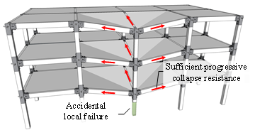
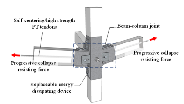
In this study, we intend to introduce the MHRPC frame system for improving both seismic and progressive collapse performances of RC frames. A schematic of the proposed MHRPC frame is shown in Figure 1, in which Figure 1b depicts the details of the beam-column joint region. The structure is assembled using precast RC beams and columns, unbonded PT tendons, energy dissipating steel angles and large rotational shear plates. It should be noted that when the structure is exposed to a specific hazard, one or more of the components may not play a major role. However, these components will become critically important to improve the structural resistance against other hazardous events. With respect to the seismic action, published experimental studies indicated that the proposed structure has a favorable self-centering capacity, minor post-earthquake damage and is easy to repair after the earthquake [14-17]. Under an earthquake scenario, the prestressing tendons, steel angles and shear plates work together to resist the seismic action. More specifically, adequate flexural strengths can be provided by the steel angles and PT tendons while sufficient shear strengths can be provided by the shear plates and PT tendons. In addition, the steel angles also serve as the energy dissipating devices, which are designed to be replaceable after the earthquake. The PT tendons also provide the self-centering capacity to the structure. When considering the progressive collapse resistance, the structure is expected to deform as shown in Figure 1a. At small deformations, the progressive collapse resistance is also provided by the flexural capacities of the beams and the compressive arch action. While at large deformations, both the steel angles and PT tendons are under tension and provide the catenary resistance to redistribute the unbalanced gravity load. The shear plates at the joint region are designed with a slotted hole to accommodate large rotation between the precast columns and beams and help to redistribute the unbalanced load. Hence, the proposed MHRPC system could provide sufficient progressive collapse resistance and alternate load paths, thereby preventing propagation of the initial failure and disproportionate collapse of the entire structural system.

(a)      Deformation of MHRPC frame under column removal scenario

(b)      Details of the beam-column joint

Figure 1. Schematic of the MHRPC frame

2.2 Experimental design

2.2.1 Design of the prototype building

In order to verify the seismic and progressive collapse performance of the proposed MHRPC frame, a six-story RC frame with a seismic design intensity of VI (i.e., the design peak ground acceleration (PGA) with a 10% probability of exceedance in 50 years is equal to 0.05g) is taken as the prototype building. Note that this prototype building has been thoroughly studied experimentally and analytically by Lin et al. [10], Ren et al. [19], and Lu et al. [20]. Three different frame structures are derived from the design, i.e., a conventional RC frame, an RC frame after implementing the progressive collapse design and a newly proposed MHRPC frame, designated as RC6, RD1, and PC6, respectively. Both cyclic tests and progressive collapse tests are conducted to compare the seismic resistance, residual deformation and progressive collapse resistance of these frames.

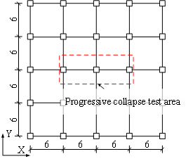
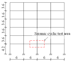
Detailed dimensions of the six-story RC frame are shown in Figure 2. The span lengths in both longitudinal and transverse directions are 6 m. The structure is considered to be fully fixed to the ground. The dead load considered on each story is 5.0 kN/m2, whereas the live load is 2.0 kN/m2. More detailed information about this prototype building have been reported by Lin et al. [9], Ren et al. [19], and Lu et al. [20]. Initially the structure is designed following the Chinese design codes (i.e., the Code for Design of Concrete Structures [21] and the Code for Seismic Design of Buildings [22]) to create the conventional RC frame, i.e., RC6.

(a)        Plan view

(b)       Elevation

Figure 2. Layout of the six-story RC frame (unit: m)

2.2.2 Progressive collapse design of RD1

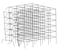
In the previous work of Lin et al. [10], nonlinear dynamic analyses of RC6 were conducted to evaluate the structural progressive collapse responses. The numerical results indicated that the prototype building would collapse under gravity load by removing any one of the columns on the first to the fifth story. Some of the typical collapse scenarios are provided in Figure 3 [10]. The outcome of this previous study suggests that RC6 does not satisfy the progressive collapse resistance requirement that is specified in DoD 2010 [11], GSA 2013[12] and the Chinese code (i.e. the Code for Anti-collapse Design of Building Structures [13]) and should be strengthened to prevent progressive collapse from happening. Note that many existing studies have proved that increasing the seismic design could also enhance the progressive collapse resistance of RC frames [10, 23]. However, the influence of the higher intensity seismic design on the improvement of the progressive collapse resistance cannot be quantified, making it hard to determine the required amount of improvement for a seismic design in order to meet the demand of progressive collapse resistance. In contrast, when the design method specified in the progressive collapse design codes is used, the improved progressive collapse resistance of a structure can be determined in a more quantitative way. For the reasons given above, RC6 is redesigned according to the tie force method provided in DoD 2010 [11] and the new structure is named as RD1.

(a)      Corner column

(b)      Edge column

(c)      Interior column

Figure 3. Collapse modes of RC6 under column removal scenarios on 1st floor (Gravity load: 1.0g) [10]

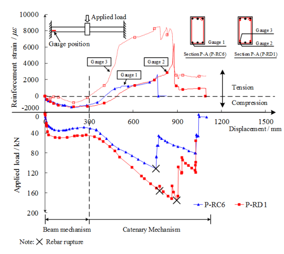
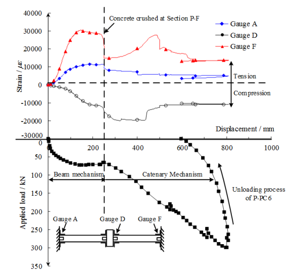
A successful progressive collapse design includes improvements in both load carrying and deformation capacities. For RC frames, the load carrying mechanisms are represented by the flexural action and compressive arch action at small deformations (beam mechanism) and the catenary action at large deformations (catenary mechanism). All the above actions help to provide alternate paths to redistribute the unbalanced load when a localized failure occurs. The deformation capacity, on the other hand, demands the structure to accommodate large deformations without losing its integrity, by which progressive collapse can be prevented. For example, a 0.20 rad of chord rotational capacity is required for RC frames as specified in DoD 2010 [11].

RD1 is designed according to the tie force method specified in DoD 2010 [11] and the required tie strength is:

(1)

in which, WF is the floor load, which can be derived from Equation 2; L1=6 m is the distance between the centers of the columns.

(2)

The design tie strength is calculated as:

(3)

in which, f = 0.75 is the strength reduction factor as specified in DoD 2010; 1.25 is the over-strength factor for the rebar, as per ASCE 41 [24]. According to DoD 2010, the design tie strength must be greater than or equal to the required tie strength:

(4)

(5)

For the prototype building considered in this study, HRB 335 (fy=300 MPa) rebar is used. The calculated As = 448 mm2/m. Hence, the resulting reinforcement area within a single span is 448¡Á6=2688 mm2. After calculating the original longitudinal reinforcement within the span, the required reinforcement would become 678 mm2 (HRB 335). After scaling, the required reinforcement in the specimens of RD1 would be 189 mm2 (HPB 300, fy=270 MPa). Hence, four 8mm-diameter bars (As=201 mm2) in total are added to Specimens of RD1. Note that the progressive collapse resistance of RD1 is also re-evaluated to be safe under different column removal scenarios [10].

Furthermore, PC6 is designed by changing the frame beams and columns in RC6 to precast members and keeping the reinforcing details unchanged. These precast beams and columns are then assembled with PT tendons, energy dissipating steel angles and shear plates.

To compare the seismic and progressive collapse performances of the abovementioned three frames, two substructures enclosed by the red dash lines in Figure 2 are extracted from the building for seismic cyclic and progressive collapse tests. For the seismic cyclic tests, the specimens representing the three frames are designated as S-RC6, S-RD1, and S-PC6, respectively. For the progressive collapse tests, the specimens are named as P-RC6, P-RD1, and P-PC6, respectively.

For both the seismic cyclic tests and the progressive collapse tests, a 1/2-scale ratio is adopted for the specimens. Published research confirmed that the critical scaling factor for RC specimens not damaging in shear is 1/4, which can well represent the resistance mechanisms and load-displacement relations of large scaled structures [25]. Hence, 1/4 [26-28], 1/3 [29-30] and 1/2 [31-33] scales were adopted in many progressive collapse tests on RC substructures. Furthermore, the 1/2-scale has been very commonly used in many published cyclic tests of beam-column joints [34-36]. Abrams [25] and Yu et al. [37] also indicated that the size effects on the collapse mechanism and resistance could be neglected when testing 1/2 scaled specimens. This provides a rationale for undertaking 1/2-scale tests in the present study.

2.3 Experimental setup

2.3.1 Seismic cyclic tests

There are many successful engineering realization of slab construction in prefabricated structures which can be used as references for the proposed MHRPC system [38]. For the purpose of not further complicating the present development work, this study does not take the slabs into consideration. Nevertheless, further studies will be conducted to investigate how the slab construction will affect the performance of the proposed MHRPC frame.

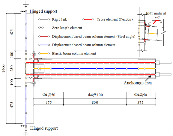
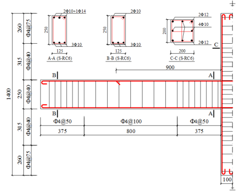
The reinforcing details of the three seismic cyclic test specimens are shown in Figures 4 and 5. In addition to the reinforcement of S-RC6 (Figure 4a), two pairs of 8 mm rebars are added to the top and bottom of the frame beams in S-RD1 after performing the progressive collapse design specified in DoD 2010 [11]. The typical sectional details of S-RD1 are given in Figure 4b, which reflects the major differences between Specimens S-RC6 and S-RD1. Details of the proposed MHRPC frame specimen (i.e., S-PC6) are shown in Figure 5. The primary design principles of this specimen are:

(a)    Reinforcement details of Specimen S-RC6

Note: Plain round bars were used in all the specimens.

(b)    Reinforcement details of Specimen S-RD1

Figure 4. Details of the seismic cyclic test RC specimens (unit: mm)

Note: Plain round bars were used in all the specimens.

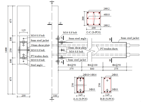
(a)    Details of Specimen S-PC6

(b)    Dimensions of the steel jackets

Figure 5. Details of the seismic cyclic test PC specimen (unit: mm)

(1)    Keeping the reinforcing details of the precast beams and columns identical to those of Specimen S-RC6.

(2)    Following the structural detailing adopted by Song et al. [16] and Lu et al. [17], the beam-column joint region is covered by 8 mm-thick steel jackets to prevent local compression failure as shown in Figures 5 and 6. The steel jackets are welded using steel plates and cast together with the beams. The main functions of the steel jackets are: (i) preventing the local compressive failure of the concrete at the beam-column interface; (ii) providing connections between the prefabricated beams and columns; (iii) serving as formwork during the construction of the beams (Figure 6).

(3)    According to the Chinese design code (i.e., the Technical Specification for Concrete Structures Prestressed with Unbonded Tendons) [39], two 12.7 mm PT tendons with a design tensile strength of 1860 MPa are inserted in the specimens as shown in Figure 5. The minimum prestressing force is determined following ACI 550.3-13 to provide a required level of self-centering capacity, which requires the flexural strength provided by the tendons being larger than that provided by the steel angles [40].

(4)    According to the design principle specified in ACI 550.3-13 [40], the ratio of the moment provided by the energy dissipating devices to the total flexural strength shall not exceed 0.5 for both positive and negative moments. Consequently, steel angles L100¡Á100¡Á8 with a thickness of 8 mm are selected as the top and seat angles and bolted to the precast beams and columns with M16 grade 8.8 bolts.

(5)    The shear plate is 10mm in thickness. The slotted hole on the shear plate allowing large deformations of the frame beams has a diameter of 18mm and a length of 53mm, which meets the deformation demands (i.e., chord rotation is equal to 0.20 rad) in the progressive collapse tests. The steel shear plates were welded to the steel jackets of the prefabricated columns, as shown in Figures 5b and 6. Note that since the beam ends are covered by the steel jackets and the shape of which are adjustable, it is not necessary for the beams to be narrower than the respective column sides.

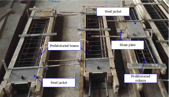
Figure 6. Formwork of the prefabricated components

The experimental setup for the seismic cyclic test is depicted in Figure 7a. The specimens are pinned at both ends of the column. The distance between the hinge supports is 1.8 m.

(a)      Setup for seismic cyclic test

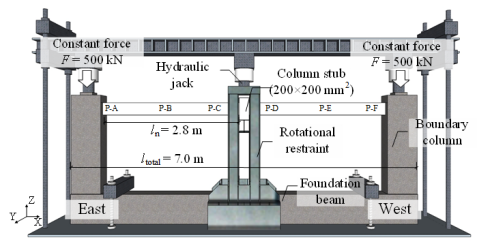
(b)      Setup for progressive collapse test

Figure 7. Experimental setup

For the seismic cyclic tests, the applied axial force is calculated according to the design axial force ratio of the column. The design axial force ratio of the middle column on the first floor is 0.85 according to the design software (the maximum axial force ratio limit for the prototype building with a seismic design intensity of VI is 0.9). Therefore, the calculated axial load is:

(6)

in which, fc =14.3 MPa is the design strength of grade C30 concrete; A = 0.4 m ¡Á 0.4 m is the area of the frame column in the prototype building; SL=2 is the scaling factor. Note that in order to keep identical boundary conditions for all the S-series specimens, this axial load was used in all the seismic cyclic tests.

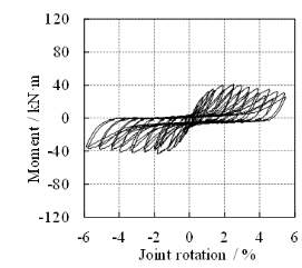
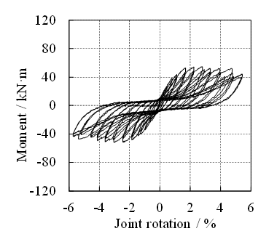
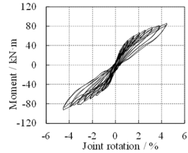
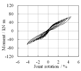
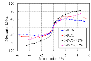
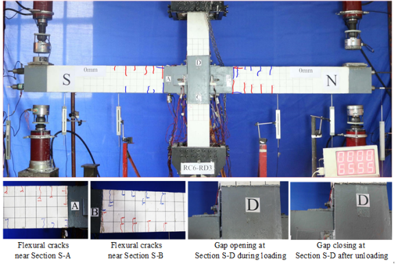
During seismic cyclic tests, a constant vertical force of 486 kN, corresponding to the design axial force ratio of 0.85, is firstly applied to the top of the column to simulate the load transferred from the upper stories. After that, the seismic forces are simulated by gradually increasing the cyclic loads at the beam ends. The loading points on the beams are 1.5 m away from the joint center. Displacement-based loading method is adopted in the tests and each level of displacement after the third cycle is cycled twice to assess the deterioration effect. The loading protocol of the seismic cyclic tests is provided in Figure 7a, which depicts the displacements at the south loading point of the S-series specimens (i.e., S-RC6, S-RD1 and S-PC6).

The relative rotation between the beam and column is calculated by measuring the displacements at the beam ends. The moments (i.e. M) and the joint rotations (i.e. q) of the specimens are calculated following Equations 7 and 8, respectively:

(7)

(8)

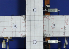
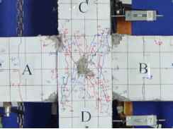
in which FS and FN are the forces recorded at the south and north loading points, respectively; dS and dN are the corresponding displacements; lF is the distance between the loading point and the joint center as shown in Figure 7a. For the convenience of describing the experimental results, four typical sections (Sections S-A to S-D) are defined on the joint specimen as shown in Figure 7a.

2.2 Progressive collapse tests

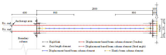
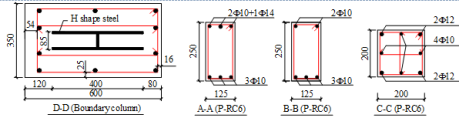
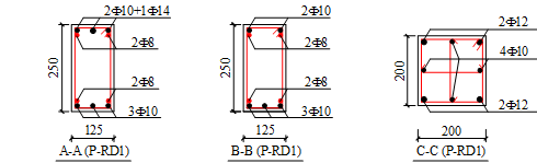
A two-span substructure on the first floor of the prototype building, which is enveloped by the red rectangle in Figure 2a, is chosen as the research object in the progressive collapse tests (Figure 6b). The reinforcing details of the tested specimens are shown in Figure 8, of which Figure 8a depicts the reinforcing details of Specimens P-RC6 and P-RD1. Figure 8b presents the details of the MHRPC specimen P-PC6. In order to ensure the strength of the boundary column, H-shaped steel is embedded in the boundary column of the specimens, as shown in Figure 8a. Note that for Specimen P-PC6, two 8 mm steel plates were cast together with the boundary columns as shown in Figure 8b. Their main function is to prevent the concrete compressive failure of the boundary columns. In a real case of the proposed MHRPC frame construction, the beam ends and the columns are also in contact with the steel jackets. Therefore, we use the steel plates at the interface area between the beams and the boundary columns to ensure the boundary conditions of the experimental tests being similar to the real situation.

(a)    Reinforcement details of Specimens P-RC6 and P-RD1

Note: Plain round bars were used in all the specimens.

(b)    Details of Specimen P-PC6

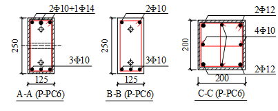
Figure 8. Details of the progressive collapse test specimens (unit: mm)

The experiments are conducted following the alternate path (AP) method as specified in the progressive collapse design guidelines [11-13]. In the AP method, column removal scenarios are assumed to study the progressive collapse responses of the remaining structures. A typical testing procedure is composed of the removal of a column and the subsequent monotonic loading, which aims to quantify the load carrying capacity of the remaining structures. Such testing protocol has been commonly used in many existing studies [27, 31, 41].

A middle column removal scenario is considered in the progressive collapse tests and the experimental setup is shown in Figure 7b. For simplicity, one directional specimens were used in the progressive collapse tests. Some researchers have conducted experiments to evaluate the bi-directional effects of beam specimens on the structural progressive collapse resistance [27]. Their results indicated that the progressive collapse resistance of the bi-directional specimen equals the summation of the individual beams lying in the perpendicular directions. Note that when considering the bi-direction effects, the external unbalanced load increases as well. It is therefore reasonable to conduct the experiments of one-directional beams to evaluate structural progressive collapse resistances [31-32, 41].

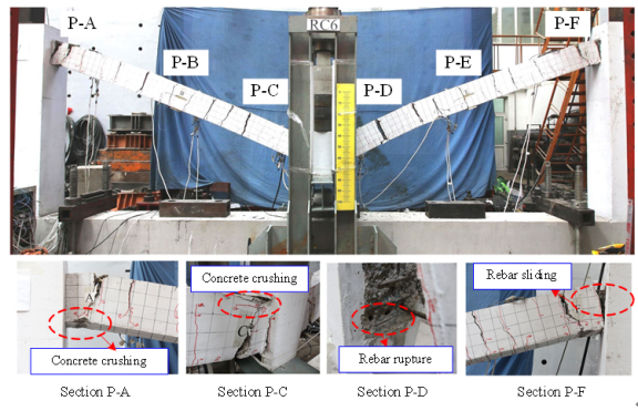
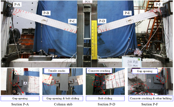
The tested two-span substructure is fixed to the strong boundary columns. In order to ensure the boundary fixities, H-shaped steel is embedded in the boundary column and two constant forces of 500 kN are applied to the top of the boundary columns. A monotonic concentrated load is then applied to the stub of the removed column to simulate the progressive collapse of the substructure subject to the middle-column removal. The loading process is displacement-controlled. At the same time, rotational restraints are installed in place of the removed column to prevent rotation of the column stub along the X and Z axes as shown in Figure 7b. Similar to the seismic cyclic test, six typical sections (Sections P-A to P-F) are defined on the specimens to better describe the experimental results as shown in Figure 7b.

2.4 Material properties

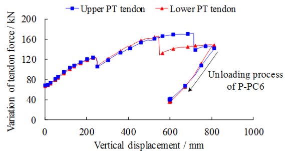
The material properties of the specimens are provided in Tables 1. Specimens S-RC6, S-RD1, P-RC6, and P-RD1 are cast with C30-grade concrete. Note that it is regulated in the Chinese code [39] that the concrete strength used in the prestressed concrete structures should not be below C40-grade (i.e., the compressive strength determined from the standard cube tests is 40 MPa). Therefore, the C40-grade concrete is used for Specimens S-PC6 and P-PC6 while the reinforcing details of the two specimens remain the same as those of S-RC6 and P-RC6, respectively. Note that concrete with the same strength is used for the RC specimens (i.e., S-RC6 and S-RD1), and hence it is rational to demonstrate the influence of the progressive collapse design on the seismic responses based on the test results of RC specimens. Plain round rebars are used for both the longitudinal and stirrup reinforcement in all the specimens. The PT tendons in Specimens S-PC6 and P-PC6 have an equivalent diameter of 12.7 mm. The experimentally measured tensile strength of the PT tendon is 1993 MPa. The prestressing forces in Specimens S-PC6 and P-PC6 are determined referring to the existing studies of self-centering prefabricated concrete frames [16-17]. The measured initial stress ratios of the PT tendons (i.e., the ratio between the initial stress and the tensile strength of the PT tendon) in Specimens S-PC6 and P-PC6 are 42% and 34%, respectively.

Table 1. Material properties

Reinforcement*1

Diameter / mm

Yield strength fy / MPa

Ultimate strength fu / MPa

Elongation ratio / %

F4

720

720

4

F8

300

460

38

F10

360

535

34

F12

369

520

39

F14

370

515

31

Steel components

Thickness / mm

Yield strength fy / MPa

Ultimate strength fu / MPa

Elongation ratio / %

8 (Steel jacket)

449

518

39

8 (Steel angle)

305

454

41

10 (Shear plate)

313

537

40

Concrete*2

Specimen

Compressive strength fcu,150mm / MPa

Specimen

Compressive strength fcu,150mm / MPa

S-RC6

28.3

P-RC6

32.5

S-RD1

28.3

P-RD1

32.5

S-PC6

51.9

P-PC6

51.9

Note: *1: Plain round bars were used in all the specimens. *2:The concrete compressive strength is determined by testing the standard cubes with a size of 150 mm ¡Á 150 mm ¡Á 150 mm, the mean value of three cubes is taken as the compressive strength.

3 Experimental results

3.1 Seismic cyclic tests

3.1.1 Experimental observations

The moment-rotation relationships of the seismic cyclic test specimens are presented in Figures 9a to 9d. Their backbone curves are compared in Figure 9e. Correspondingly, their experimental observations are presented in Figures 10 and 11, of which, Figure 10 depicts the failure modes of the RC specimens (i.e., S-RC6 and S-RD1) and Figure 11 displays the experimental observations of the PC specimen (i.e., S-PC6).

(a)    S-RC6

(b)    S-RD1

(c)    S-PC6 (initial stress ratio: 42%)

(d)    S-PC6 (initial stress ratio: 20%)

(e)    Comparison of the backbone curves

Figure 9. Comparison of the seismic cyclic test results

The final failure mode of S-RC6 was a typical ¡°strong column-weak beam¡± failure as shown in Figure 10a. Damage of the specimen was mainly found at the joint area between the beam and column while there was no damage to the joint itself or in the columns. In contrast, for Specimen S-RD1, at the joint rotation q = ¡À1.74% (i.e., beam end displacement d = 30 mm), diagonal cracks appeared in the joint region of S-RD1. After that, concrete crushed at Sections S-A and S-B at q = ¡À2.28% (d = 40 mm). At the same time, flexural cracks were found near Sections S-C and S-D on the column.

(a)    S-RC6

(b)    S-RD1

Figure 10. Crack distribution of Specimens S-RC6 and S-RD1

The final crack distribution of Specimen S-RD1 is shown in Figure 10b, demonstrating a severe damage at the frame column and joint area due to the strengthening of the frame beams after progressive collapse design is implemented. Such a failure mode of S-RD1 indicates that the column and joint may fail before beams in RD1 under seismic action, suggesting that S-RD1 could no longer meet the seismic design requirement of ¡°strong column-weak beam¡±. Note that according to the previous study of Lin et al. [10], a seismic re-design following a progressive collapse design (i.e., increasing the strength of corresponding columns) can indeed improve the seismic performance of the structure. Nevertheless, such a design process based on different design codes will result in more than 50% material consumption in form of increased amount of longitudinal reinforcement, which obviously is not a cost-effective solution.

Shown in Figure 11 is the crack distribution of the MHRPC specimen S-PC6. Different from the RC specimens, Specimen S-PC6 deformed elastically in the initial stage of the cyclic loading. At q = ¡À 1.70% (d = 30 mm), gaps opened at the interface area between the beam and column and some flexural cracks formed near Sections S-A and S-B. However, after unloading at the end of each cycle, the abovementioned flexural cracks and gaps were closed due to the re-centering forces provided by the PT tendons (Figure 11). Note that a larger beam end displacement would result in a wider gap. Upon completion of the cyclic tests, the beams of S-PC6 returned to their original positions. In addition, the cracks on the beams eventually closed and the residual deformation of this specimen was very small, demonstrating an excellent resilient performance. Note that since the joint area of Specimen S-PC6 was protected with 8 mm-thick steel jacket, the joint shear failure, which was found during the test of Specimen S-RD1, was avoided.

Figure 11. Cyclic test result of Specimen S-PC6 (no residual deformation after the test)

As the residual deformation of Specimen S-PC6 was small and the concrete components were free from damage, this specimen was re-tested after the first cyclic test. In the second test of Specimen S-PC6, the initial stress ratio of the PT tendons was reduced from 42% to 20% and the energy dissipating steel angles were replaced. It was found that the experimental observations of the second test were similar to those of the first one. Also, the specimen was re-centered after the test, which satisfied the demand of resilience. For the two tests of Specimen S-PC6, the relationships between the resultant PT tendon force (i.e., Ttotal) and the joint rotation are depicted in Figure 12. Note that Ttotal is calculated by the following equation:

(9)

in which Tup and Tdown are the internal forces in the upper and lower PT tendons, respectively. Figure 12 indicates that the initial stress ratio of the PT tendon has little or no effect on the variation of the resultant tendon force during the loading process. Moreover, when the initial stress ratio is relatively low (i.e., 20%), the loss of prestressing after the cyclic loading is also smaller than that with the high initial stress ratio (i.e., 42%).

(a)      First test of S-PC6 (initial stress ratio: 42%)

(b)      Second test of S-PC6 (initial stress ratio: 20%)

Figure 12. Variation of resultant tendon force during the seismic cyclic tests of S-PC6

By comparing the moment-rotational relationship of the RC and PC specimens, the results indicate that: (1) For the RC specimens, after implementing the progressive collapse design, the flexural capacities of the frame beams in S-RD1 are increased by approximately 30%, compared to that of S-RC6. (2) For the PC specimens, the initial stress ratio of the PT tendons has significant effects on their initial stiffness and flexural yield strength. It is worth noting that S-PC6 has a stable post-yielding stiffness and a small residual deformation, which are critical to control the failure modes [42] and resilient performance.

3.1.2 Failure mechanism analyses

(A)   RC specimens (S-RC6 and S-RD1)

The rebar strains of Specimens S-RC6 and S-RD1 are compared in Figure 13, of which Figures 13a and 13b are for the beam and column reinforcement, respectively. After implementing the progressive collapse design, the maximum strain of the beam reinforcement of Specimen S-RD1 decreases to approximately 46% compared to that of Specimen S-RC6. In contrast, the maximum strain of the column reinforcement increases to approximately 40%. In addition, because the joint region of S-RD1 was severely damaged under the cyclic load, the strains of the column reinforcement in S-RD1 were not as symmetric as those in S-RC6. The failure mode of S-RC6 can be regarded as the favorable ¡°strong column-weak beam¡± failure while that of S-RD1 is more like the unfavorable ¡°strong beam-weak column¡± failure, which may potentially weaken the structural seismic performance. This finding is consistent with the results of the structural system-level performance evaluation conducted by Lin et al. [10].

(a)    Section S-A (on the beam)

(b)    Section S-C (on the column)

Figure 13. Rebar strains of Specimens S-RC6 and S-RD1

(B)   MHRPC specimen (S-PC6)

The strains of the steel angle and shear plate of Specimen S-PC6 are shown in Figure 14. In Figure 14a, the blue color is used to indicate the pre-yielding stage of the steel angle while the red color denotes the post-yielding stage of the steel angle. When the joint rotation reached 1.6%, the steel angle was found to have yielded and started to dissipate energy (Figure 14a). Compared with the steel angle, the shear plate remained elastic under the seismic cyclic load (Figure 14b).

(a)    Strain of the steel angle

(b)    Strain of the shear plate

Figure 14. Strains of the steel angle and shear plate in Specimen S-PC6

3.2 Progressive collapse tests

3.2.1 Experimental observations

The load-displacement curves derived from the progressive collapse tests are compared in Figure 15. The loading process of all the specimens can be divided into two stages, i.e., beam mechanism and catenary mechanism, which are two key resisting mechanisms to balance the applied load under the column removal scenarios. During the progressive collapse test of an RC beam, the unbalanced load is resisted by the beam mechanism at small deformations. At this stage, the flexural strengths of the beams, in conjunction with the compressive arch action in the specimen, provide the resistance to progressive collapse. Moreover, the catenary action at the large deformation stage serves as the last resisting mechanism in progressive collapse scenarios, which utilizes the tensile forces from the rebars to balance the applied load. According to DoD 2010 [11], 0.20 rad of chord rotation is used to define the deformation limit of the specimens. As such, two key points can be identified on the load-displacement curves shown in Figure 15: (1) the peak point of the beam mechanism (Db, Fb) and (2) the point corresponding to the chord rotation of 0.20 rad (D0.20, F0.20), where D and F denote the displacement and force, respectively. Note that the displacement at the 0.20 rad chord rotation (i.e., D0.20) is 560 mm. The corresponding values of the two key points are compared in Table 2 for all the specimens.

Table 2. Comparison of progressive collapse resistance of different specimens

Specimen

Db / mm

Fb / kN

Percentage increase / %

F0.20 / kN

Percentage increase / %

P-RC6

97

35

/

80

/

P-RD1

98

50

43%

105

31%

P-PC6

145

72

105%

192

140%

Figure 15. Comparison of the progressive collapse test results

The final failure mode of Specimen P-RC6 under the middle-column removal scenario is shown in Figure 16. Referring to Figures 15 and 16, at displacements of 68 mm and 80 mm, concrete crushing occurred at Sections P-A and P-F of P-RC6, respectively (Figure 16). The specimen reached its peak resistance of the beam mechanism (i.e., Fb =35 kN) at displacement of 97 mm. Afterwards, concrete crushing were also found at Sections P-C and P-D when the displacement reached 100 mm (Figure 16). The transition stage from the beam mechanism to the catenary mechanism is between 200 mm to 350 mm. After that, the vertical load was resisted through the catenary mechanism. The beams were under tension and the tensile cracks were distributed along the full length of the beams. At the required chord rotation, the resistance of the specimen reached F0.20=80 kN. At displacement of 756 mm, a rebar near the column stub ruptured, which results in a sudden drop of the external load from 112 kN to 45 kN. With further increase in displacement, all of the continuous rebars near the column stub ruptured (at Section P-D) and rebar sliding was clearly noticed (Section P-F), correspondingly the load dropped to zero.

Figure 16. Final failure mode of Specimen P-RC6

The loading process and the final failure mode of Specimen P-RD1 were quite similar to those of P-RC6. The Fb and F0.20 were 50 kN and 105 kN, respectively. By comparing the load-displacement curves of P-RC6 and P-RD1, it can be found that the characteristic bearing capacities of P-RD1 (i.e., Fb and F0.20) was higher than that of P-RC6: Fb increased by 43% while F0.20 increased by 31%. Therefore, including the progressive collapse design can significantly improve the resistances at both beam mechanism and catenary mechanism.

The final failure mode of the MHRPC specimen P-PC6 in the progressive collapse test is shown in Figure 17a. The variation of the PT tendon forces is displayed in Figure 17b. When the displacement reached 25 mm, gaps opened at the interface area between the precast beam and the boundary column (Section P-A). The applied load reached the peak resistance of the beam mechanism  (i.e., Fb =72 kN) at displacement of 145 mm. After that, the external load remained a relatively stable value until the displacement reached 250 mm. Then concrete crushing and reinforcement buckling were identified at Section P-F of the specimen as shown in Figure 17a. At the same time, the load dropped slightly and so did the tensile forces of the upper and lower PT tendons (Figure 17b). As the displacement increased further, the loading process entered the stage of catenary mechanism and the resistance continued to increase as well. When the displacement reached 545 mm, a relative slippage occurred between the lower PT tendon and its anchor, which also resulted in a sudden drop of the PT tendon force. Note that no rupture was found in the PT tendon and the tensile force continued to increase again after the drop. Corresponding to this PT tendon anchor slippage, there was a small oscillation on the load-displacement curve, after which the load increased again. At displacement of 712 mm, the slippage between the upper PT tendon and its anchor occurred, which also led to a drop of the PT tendon force and a minor oscillation on the load-displacement curve. After the displacement of P-PC6 reached 800 mm, we intended to continue the test to a complete failure of the specimen. However, a sudden and alarming failure of the PT tendons in this specimen was not permitted to happen in the laboratory due to the health and safety concerns. In addition, the displacement of P-PC6 had notably exceeded the required displacement of 560 mm (i.e., 0.20 rad chord rotation). Consequently, the loading process was terminated at displacement of 800 mm. It is worth noting that the external load remained a growing trend as the displacement increased when the test was terminated. The load-displacement relationship corresponding to the unloading phrase is also presented in Figure 15.

(a)    Final failure mode of P-PC6

(b)    Variation of the tendon forces

Figure 17. Progressive collapse test results of P-PC6

By comparing the load-displacement curves of the progressive collapse test specimens in Figure 15, the results indicate that P-PC6 can provide sufficient progressive collapse resistance under the column removal scenario. The Fb and F0.20 of Specimen P-PC6 were 72 kN and 192 kN, respectively. The Fb increased by 105% and F0.20 increased by 140% compared to Specimen P-RC6, which were also much greater than those of Specimen P-RD1. It can be concluded that the MHRPC specimen can provide a stably growing resistance as the displacement increases and meet the code requirement of the chord rotational capacity at the stage of large deformation.

3.2.2 Failure mechanism analyses

(A)   RC specimens (P-RC6 and P-RD1)

The strains of the bottom beam reinforcement at Section P-A of Specimens P-RC6 and P-RD1 are compared in Figure 18. The load-displacement curves are also included to match the strain development. The bottom reinforcement was under compression at the beam mechanism stage. By contrast, during the catenary mechanism, the reinforcement strain changed from compression to tension. The progressive collapse resistances at this stage were mainly contributed by the tensile forces of the longitudinal rebars. The reinforcement strains experienced a sudden drop at the point of rebar rupture as shown in Figure 18.

Figure 18. Strains of the bottom beam rebars at Section P-A of Specimens P-RC6 and P-RD1

(B)   MHRPC specimen (P-PC6)

During the progressive collapse test, the strain gauge readings on the top steel angles at Sections P-A, P-D, and P-F of P-PC6 are shown in Figure 19. Under the concentrated vertical load, the top steel angles at Sections P-A and P-F were under tension, while the top steel angle at Section P-D was under compression. The strain curves indicate that the steel angles have already yielded at the beam mechanism stage. There was a sudden drop in the strain curve of Gauge F at Section P-F, which was triggered by concrete crushing at Section P-F due to the compressive arch action.

Figure 19. Strains of the steel angles in Specimen P-PC6

The strain-displacement relationships of the gauges along the height of the shear plate at Section P-D are provided in Figure 20. The results indicate that the shear plate acted as a cantilever beam and resisted the load transferred from the bolt during the progressive collapse test. According to the measuring values from Gauge S-1, it is evident that the shear plate yielded at the catenary mechanism stage of the loading process.

Figure 20. Strains of the shear plates in Specimen P-PC6

4. Numerical simulation of MHRPC specimens based on OpenSees

Many successfully numerical studies simulating the seismic and progressive collapse responses of RC structures using various finite element (FE) codes have been reported in the literature [34, 43-45]. In this study, the abovementioned seismic cyclic and progressive collapse tests of the MHRPC substructures are simulated using the open source FE software package OpenSees [46]. To simulate the seismic response of post-tensioned precast concrete frames, El-Sheikh et al. [47] proposed to use the fiber beam elements, accompanied by a series of spring models. Existing studies [18, 48-49] have also proved that OpenSees can simulate the cyclic behavior of similar types of self-centering structures. Furthermore, OpenSees has been used by many other researchers to simulate the progressive collapse response of RC frame beams under column removal scenarios [50-52]. In consequence, the use of OpenSees in simulating the cyclic and progressive collapse tests can be justified.

4.1 Simulation of seismic cyclic tests

The FE model for simulating the seismic cyclic tests is shown in Figure 21a. Each structural component of the MHRPC specimen is modeled by various types of elements with different material properties in OpenSees. The precast beam and column are modeled by the displacement-based beam-column elements in OpenSees. In order to model the steel jacket at the beam ends and the joint region, elastic beam elements are used in these parts of the FE model. A series of zero-length spring elements are used to simulate the gap opening and closing behaviors at the interface areas between the beams and columns. According to the experimental results, when the gap opened at the joint area, it was found that the precast beam rotated along the contact point of the steel jackets (Figure 21a). Therefore, the corresponding zero-length elements are also arranged at the contact points. The Elastic-No Tension (ENT) material is adopted for these zero-length elements. When the ENT material is under compression, a relatively large elastic modulus (i.e., 2 ¡Á 1011 Pa) is assigned to simulate the contact between the steel jackets. The PT tendons in the specimen are simulated using truss elements with Steel02 material in OpenSees. The initial stress is modeled by setting the parameter $sigInit of Steel02 material. The variation of the PT tendon force during the test is modeled according to Guo et al. [48]. At the ends of the frame beam, the PT tendon elements are connected to the precast beam elements with rigid links at the points where the PT tendons are anchored. The energy dissipating steel angles are also modeled with displacement-based beam-column elements. These elements are connected to the beams and columns where the high strength bolts are located. A series of rigid links are used for the connection to ensure that the geometric configurations of the steel angles in the FE model are exactly identical to the tested specimen (Figure 21a). Moreover, the shear plates are modeled as shear links in the FE model.

(a)    Numerical model for the seismic cyclic test

(b)    Numerical model for the progressive collapse test

Figure 21. FE models of the MHRPC specimens (unit: mm)

Using the proposed FE model, two seismic cyclic tests of Specimen S-PC6 are simulated. The numerical predictions are compared with the experimental results in Figure 22. The comparison indicates that the proposed FE model can accurately predict the seismic cyclic responses of the MHRPC specimens with different initial stress ratios. In addition, the simulated variations of the resultant PT tendon forces are also consistent with the experimental results.

(a)    Specimen S-PC6 (Initial stress ratio: 42%)

(b)    Specimen S-PC6 (Initial stress ratio: 20%)

Figure 22. Numerical results of seismic cyclic tests of Specimen S-PC6

4.2 Simulation of progressive collapse test

The FE model in OpenSees for the progressive collapse test is shown in Figure 21b. Most components in this model follow the similar modeling strategies as the FE model for the seismic cyclic test (Figure 21a). The major difference between the two FE models is the element type used for simulating the PT tendons. In the progressive collapse test, the dowel effects of the PT tendons play a significant role during the test, which cannot be simulated by using the truss element. As a result, the displacement-based beam-column elements are adopted to model the PT tendons.

Based on the proposed FE model, the progressive collapse test of Specimen P-PC6 is simulated and compared with the experimental results in Figure 23. The comparison indicates that the proposed model is able to predict, in good agreement, the progressive collapse behavior of Specimen P-PC6 at both stages of the beam and catenary mechanisms.

Figure 23. Numerical results of progressive collapse test of P-PC6

5 Conclusion

Building multi-hazard resistant structures has become the future development trend of civil engineering research. In order to improve the multi-hazard resistance of multi-story RC frame structures, a novel prefabricated frame system (i.e., MHRPC frame) is proposed in this study. Three different frames, i.e., a conventional RC frame, an RC frame after implementing the progressive collapse design and a newly proposed MHRPC frame are tested. Their structural seismic and progressive collapse performances are compared in some detail. Subsequently, the seismic cyclic tests and the progressive collapse test of the MHRPC specimens are simulated based on the open source FE software OpenSees. Following are the main conclusions of this study:

(1)    The influence of progressive collapse design on the seismic performance of RC frames was experimentally studied for the first time. The experimental results of Specimens S-RD1 and P-SD1 show that implementing the progressive collapse design can effectively enhance the progressive collapse resistance of RC frames. However, the frame beam could be over-strengthened when designed for progressive collapse, which may lead to severe damage to the joint area and the frame column, resulting in a potential unfavorable ¡°strong beam-weak column¡± failure mode.

(2)    The seismic cyclic tests reveal that the MHRPC specimen S-PC6 has much smaller residual deformations and less component damage compared to the RC specimens. Moreover, Specimen S-PC6 remains a stable post-yielding stiffness, which is beneficial to the control of structural deformation and energy dissipating mode. Following a simple repair, the MHRPC specimen can recover and maintain a stable seismic performance, which satisfies the demand of resilience.

(3)    The progressive collapse test of a MHRPC substructure, which is not found in the existing literature, was successfully conducted. Under the middle column removal scenario, the MHRPC specimen P-PC6 has a much higher progressive collapse resistance than the RC specimens, which demonstrates a superior load redistribution capacity of this newly proposed structural system. In addition, the MHRPC specimen also meets the requirement of the chord rotational capacity as regulated in DoD 2010 [11].

(4)    A numerical method suitable for simulating both seismic and progressive collapse responses of the MHRPC frame specimens was proposed and validated against the experimental results.

To sum up, the proposed MHRPC frame system has the characteristics of large rotation, low damage, self-centering and ease of repair, thereby meeting the requirement of multi-hazard resilience of RC frame structures against both earthquake actions and progressive collapse. The outcome of this study can serve to provide an initial reference for the future multi-hazard resistant design of building structures.

Acknowledgement

The authors are grateful for the financial support received from the National Natural Science Foundation of China (No. 51778341), the National Key Research and Development Program of China (No. 2016YFC0701400), and the European Community's Seventh Framework Program (Marie Curie International Research Staff Exchange Scheme, Grant No. 612607).

References

[1]      Zhao B, Taucer F, Rossetto T. Field investigation on the performance of building structures during the 12 May 2008 Wenchuan earthquake in China. Eng Struct 2009; 31(8): 1707-1723.

[2]      Sozen M, Thornton C, Corley W, Sr P. The Oklahoma City bombing: structure and mechanisms of the Murrah Building. J Perform Constr Facil 1998; 12(3): 120-136.

[3]      Ellingwood BR. Mitigating risk from abnormal loads and progressive collapse. J Perform Constr Facil 2006; 20(4): 315-323.

[4]      Kotsovinos P, Usmani A. The World Trade Center 9/11 disaster and progressive collapse of tall buildings. Fire Tech 2013; 49(3): 741-765

[5]      Li Y, Ahuja A, Padgett JE. Review of methods to assess, design for, and mitigate multiple hazards. J Perform Constr Facil 2011; 26(1): 104-117.

[6]      Fascetti A, Kunnath SK, Nistic¨° N. Robustness evaluation of RC frame buildings to progressive collapse. Eng Struct 2015; 86: 242-249.

[7]      Li M, Sasani M. Integrity and progressive collapse resistance of RC structures with ordinary and special moment frames. Eng Struct 2015; 95: 71-79.

[8]      Livingston E, Sasani M, Bazan M, Sagiroglu S. Progressive collapse resistance of RC beams. Eng Struct 2015; 95: 61-70.

[9]      American Concrete Institute (ACI). Building code requirements for structural concrete (ACI 318-11) and commentary (318R-11). Detroit, MI; 2011.

[10]  Lin KQ, Li Y, Lu XZ, Guan H. Effects of seismic and progressive collapse designs on the vulnerability of RC frame structures. J Perform Constr Facil 2017; 31(1): 04016079.

[11]  Department of Defense (DoD). Design of structures to resist progressive collapse. Unified facility criteria, UFC 4-023-03, Washington, DC; 2010.

[12]  General Services Administration (GSA). Alternate path analysis and design guidelines for progressive collapse resistance. Washington, DC; 2013.

[13]  China Association for Engineering Construction Standardization (CECS). Code for anti-collapse design of building structures. CECS 392: 2014, Beijing; 2015. (in Chinese)

[14]  Priestley MN, Tao JR. Seismic response of precast prestressed concrete frames with partially debonded tendons. PCI J 1993; 38(1): 58-69.

[15]  Wolski M, Ricles JM, Sause R. Experimental study of a self-centering beam-column connection with bottom flange friction device. J Struct Eng 2009; 135(5): 479-488.

[16]  Song LL, Guo T, Chen C. Experimental and numerical study of a self©\centering prestressed concrete moment resisting frame connection with bolted web friction devices. Earthq Eng Struct Dyn 2014; 43(4): 529-545.

[17]  Lu XL, Cui Y, Liu JJ, Gao WJ. Shaking table test and numerical simulation of a 1/2©\scale self©\centering reinforced concrete frame. Earthq Eng Struct Dyn 2015; 44(12): 1899-1917.

[18]  Song LL, Guo T, Cao ZL. Seismic response of self-centering prestressed concrete moment resisting frames with web friction devices. Soil Dyn Earthq Eng 2015; 71: 151-162.

[19]  Ren PQ, Li Y, Lu XZ, Guan H, Zhou YL. Experimental investigation of progressive collapse resistance of one-way reinforced concrete beam-slab substructures under a middle-column-removal scenario. Eng Struct 2016; 118: 28-40.

[20]  Lu XZ, Lin KQ, Li Y, Guan H, Ren PQ, Zhou YL. Experimental investigation of RC beam-slab substructures against progressive collapse subject to an edge-column-removal scenario. Eng Struct 2017; 149(15): 91-103.

[21]  Ministry of Housing and Urban-Rural Development of the People¡¯s Republic of China (MOHURD). Code for design of concrete structures. GB50010-2010, Beijing, China; 2010. (in Chinese)

[22]  Ministry of Housing and Urban-Rural Development of the People¡¯s Republic of China (MOHURD). Code for seismic design of buildings. GB50011-2010, Beijing, China; 2010. (in Chinese)

[23]  Hayes Jr JR, Woodson SC, Pekelnicky RG, Poland CD, Corley WG, Sozen M. Can strengthening for earthquake improve blast and progressive collapse resistance?. J Struct Eng 2005; 131(8): 1157-1177.

[24]  ASCE/SEI Standard 41-17. Seismic evaluation and retrofit of existing buildings. Structural Engineering Institute, American Society of Civil Engineers; 2017.

[25]  Abrams DP. Scale relations for reinforced concrete beam-column joints. ACI Struct J 1987; 84: 502-512.

[26]  Pham XD, Tan KH. Experimental study of beam-slab substructures subjected to a penultimate-internal column loss. Eng Struct 2013; 55: 2-15.

[27]  Qian K, Li B, Ma JX. Load-carrying mechanism to resist progressive collapse of RC buildings. J Struct Eng 2015; 141(2): 04014107.

[28]  Qian K, Li B. Load-resisting mechanism to mitigate progressive collapse of flat slab structures. Mag Concrete Res 2015; 67(7): 349-363.

[29]  Qian K, Li B. Quantification of slab influences on the dynamic performance of RC frames against progressive collapse. J Perform Constr Facil 2015; 29(1): 04014029.

[30]  Yi WJ, He QF, Xiao Y, Kunnath SK. Experimental study on progressive collapse-resistant behavior of reinforced concrete frame structures. ACI Struct J 2008; 105(4): 433-439.

[31]  Yu J, Tan KH. Structural behavior of RC beam-column sub-assemblages under a middle column removal scenario. J Struct Eng 2013; 139(2): 233-250.

[32]  Alogla K, Weekes L, Augusthus-Nelson L. A new mitigation scheme to resist progressive collapse of RC structures. Constr Build Mater 2016; 125: 533-545.

[33]  Xiao Y, Kunnath S, Li F W, Zhao YB, Lew HS. Collapse test of three-story half-scale reinforced concrete frame building. ACI Struc J 2015; 112(4): 429-438.

[34]  Xie LL, Lu XZ, Guan H, Lu X. Experimental study and numerical model calibration for earthquake-induced collapse of RC frames with emphasis on key columns, joints, and the overall structure. J Earthq Eng 2015; 19(8): 1320-1344.

[35]  Tsonos AG. Cyclic load behavior of reinforced concrete beam-column sub-assemblages of modern structures. ACI Struct J 2007; 104(4): 468-478.

[36]  Mirzabagheri S, Tasnimi AA, Mohammadi MS. Behavior of interior RC wide and conventional beam-column roof joints under cyclic load. Eng Struct 2016; 111: 333-344.

[37]  Yu J, Tan KH. Experimental and numerical investigation on progressive collapse resistance of reinforced concrete beam column sub-assemblages. Eng Struct 2013; 55: 90-106.

[38]  Kurama YC, Sritharan S, Fleischman RB, Restrepo JI, Henry RS, Cleland NM, Ghosh SK, Bonelli P. Seismic-resistant precast concrete structures: state of the art. J Struct Eng 2018; 144(4): 03118001.

[39]  Ministry of Housing and Urban-Rural Development of the People¡¯s Republic of China (MOHURD). Technical specification for concrete structures prestressed with unbonded tendons. JGJ 92-2004, Beijing, China; 2005. (in Chinese)

[40]  American Concrete Institute (ACI). 550.3-13. Design specification for unbonded post tensioned precast concrete special moment frames satisfying ACI 374.1 and Commentary. Farmington Hills, MI; 2013.

[41]  Su YP, Tian Y, Song X. Progressive collapse resistance of axially-restrained frame beams. ACI Struct J 2009; 106(5): 600-607.

[42]  Ye LP, Lu XZ, Ma QL, Cheng GY, Song SY, Miao ZW, Pan P. Study on the influence of post-yielding stiffness to the seismic response of building structures. Proc. the 14th World Conference on Earthquake Engineering, October 12-17, 2008, Beijing, China, CDROM.

[43]  Sasani M, Werner A, Kazemi A. Bar fracture modeling in progressive collapse analysis of reinforced concrete structures. Eng Struct, 2011; 33(2): 401-409.

[44]  Kim Y, Kabeyasawa T, Matsumori T, Kabeyasawa T. Numerical study of a full©\scale six©\story reinforced concrete wall©\frame structure tested at E-Defense. Earthq Eng Struct Dyn 2012; 41(8): 1217-1239.

[45]  Karimzadeh S, Askan A, Yakut A, Ameri G. Assessment of alternative simulation techniques in nonlinear time history analyses of multi-story frame buildings: A case study. Soil Dyn Earthq Eng 2017; 98: 38-53.

[46]  Mazzoni S, McKenna F, Scott MH, Fenves GL. The open system for earthquake engineering simulation (OpenSees) user command-language manual. 2006.

[47]  El-Sheikh MT, Sause R, Pessiki S, Lu LW. Seismic behavior and design of unbonded post-tensioned precast concrete frames. PCI J 1999; 44(3): 54-71.

[48]  Guo T, Song LL, Zhang G. Numerical simulation of the seismic behavior of self-centering steel beam-column connections with bottom flange friction devices. Earthq Eng Eng Vib 2011; 10(2): 229-238.

[49]  Mirzaie M, Bahaari MR, Emam SH. Numerical simulation of the new post tensioned column base with bolted T-stubs. ISIJ international 2014; 54(1), 179-187.

[50]  Bao Y, Kunnath SK, El-Tawil S, Lew H. Macromodel-based simulation of progressive collapse: RC frame structures. J Struct Eng 2008; 134(7): 1079-1091.

[51]  Talaat M, Mosalam KM. Modeling progressive collapse in reinforced concrete buildings using direct element removal. Earthq Eng Struct Dyn 2009; 38(5): 609-634.

[52]  Kazemi-Moghaddam A, Sasani M. Progressive collapse evaluation of Murrah Federal Building following sudden loss of column G20. Eng Struct 2015; 89: 162-171.


* Corresponding author, Email: luxz@tsinghua.edu.cn

Introduction
Research
Application
Teaching
Publications
Download
Issues
Others


Our Lab

Collapse Prevention Committee