|
4.2 Specimens tested under progressive collapse
loading
4.2.1 Test results
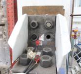
(A) Specimen
B-C
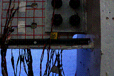
The maximum displacement of the middle column
of Specimen B-C reached 250 mm, and the corresponding beam-to-column rotation
angle was q = 0.089 rad. The overall
deformation of the specimen after the test is shown in Figure 14.
|

|
|
Figure 14
Overall deformation of Specimen B-C after the test
|
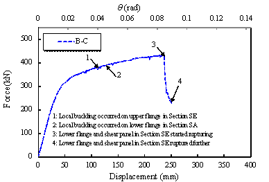
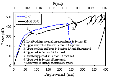
The load-displacement curve of the middle
column of Specimen B-C is shown in Figure 15. The typical physical phenomena
associated with the progression of damage are marked on the same figure and
are illustrated in Figure 16:
|
|
|
Figure 15
Load (F)-displacement (D) relationship
of Specimen B-C
|
|
|
|
|
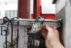
(a)
Local buckling
occurred on the upper flange in Section SE (1, D =
91 mm, F = 366.4 kN)
|
(b)
Local buckling
occurred on the lower flange in Section SA (2, D =
96 mm, F = 369.1 kN)
|
|

|

|
|
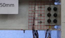
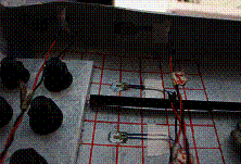
(c)
Lower flange
and shear panel in Section SE started rupturing (3, D =
237 mm, F = 429.3 kN)
|
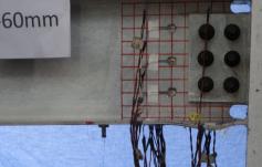
(d)
Lower flange
and shear panel in Section SE ruptured further (4, D =
250 mm, F = 227.9 kN)
|
|
Figure 16
Typical phenomena of Specimen B-C
|
(1)
Referring to Figure
16a, when D
= 91 mm, local buckling occurred on the upper flange of the beam
in Section SE (Figure 14). Considering the beam geometry and its material
properties, the deformation level at which local buckling initiated is consistent
with the predicted values in fully-restrained beam-to-column connections [48,
49].
(2)
From Figure 16b, local buckling
occurred on the lower flange of the beam in Section SA (Figure 14) at a displacement
D
= 96 mm.
(3)
Fracture initiation at the
lower flange and shear panel in Section SE occurred at a corresponding displacement
D
= 237 mm, indicating a peak force value of 431.6 kN.
(4)
Finally, at D = 250 mm, the joint
lost more than 40% of its load carrying capacity due to progression of fracture
of the lower flange and the shear panel in Section SE. At this point, the
test was terminated.
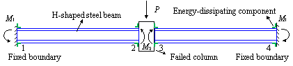
For Specimen B-C, due to the compressive arch
action [50, 51] developed during the vertical loading process (Figure 17),
the axial force in the beam increased, leading to the local buckling of the
beam at q
= 0.033
rad. Similar local buckling phenomena were also found in the
two progressive collapse tests of bolt-welded connection frame joints (Specimens
SI-WB and SI-WB-2) conducted by Li et al. [52]. The dimensions of the beams
in these two specimens (SI-WB and SI-WB-2), namely H300ˇÁ150ˇÁ6ˇÁ8, are very
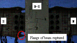
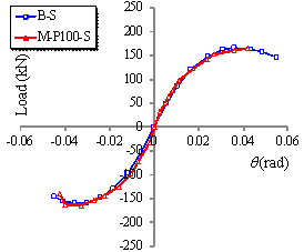
similar to those tested in this study. For Specimen B-S, the flange of the
beam exhibited local buckling at q =
0.019 rad. Nevertheless, such a local
buckling was still undetectable until the angle reached 0.036 rad, which can
be observed in Figures 10a and 10b. To sum up, the local buckling phenomena
of Specimens B-S and B-C are considered conventional. In addition, the H-shaped
steel beams adopted in Specimens B-S and B-C are scaled down
from the prototype components in Building L. The width-thickness ratio of
the beam flange meets the requirement of Article 8.4.2 of GB 50017-2017 [40],
which satisfies the requirement for local stability of steel components. Additionally,
according to the cyclic test results, the beamˇŻs moment
resistance of Specimen B-S
was greater than 80% of the beamˇŻs flexural strength
at q =
0.04 rad, which meets the requirement of AISC 341-16 [39] for
composite special moment frames.
|
|
|
(a) Resistance mechanism of H-shaped steel beams at initial loading
stage
|
|
|
|
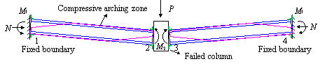
(b) Resistance mechanism of H-shaped steel beams at compressive
arch action stage
|
Figure 17 Compressive
arch action in H-shaped steel beams at small deformation stage under concentrated
load
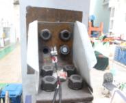
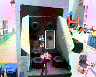
(B) Specimen
M-P100-C
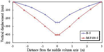
The maximum displacement of Specimen M-P100-C
reached 399 mm, and the corresponding beam-column rotation angle was q = 0.143 rad. The overall deformation of the specimen after the test is shown
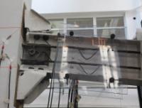
in Figure 18. A comparison of the final vertical deformations of Specimen
B-C and Specimen M-P100-C is shown in Figure 19. It is apparent that Specimen
M-P100-C that employs the proposed beam-to-column configuration deformed nearly
two times of Specimen B-S prior to connection failure. Therefore, the catenary
action occurs more effectively. Note that catenary action is significant for
progressive collapse design [53-55].
|
|
|
Figure 18 Overall deformation of Specimen M-P100-C after the
test
|
|
|
|
Figure 19 Final vertical deformation development of the specimens
|
The physical phenomena corresponding to the damage initiation and
progression of Specimen M-P100-C are depicted on the associated load-displacement
curve of the middle column shown in Figure 20. Bending moments in Specimen M-P100-C are primarily provided by
the energy-dissipating components and pre-stressed steel strands. Specifically, the energy-dissipating
components can provide a steadily increasing bending
moment [34]. The pre-stressed steel strands can provide the effective tying force and contribute
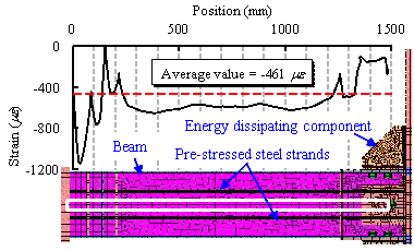
to the catenary action. Figure 21 shows the axial
forces in the pre-stressed steel strands in relation to the stages of load
rebound of Specimen M-P100-C, which shows the characteristics different from
that of Specimen B-C. These phenomena of Specimen M-P100-C are illustrated in Figure 22.
|
|
|
Figure 20
Load (F)-displacement (D) relationship
of Specimen M-P100-C
|
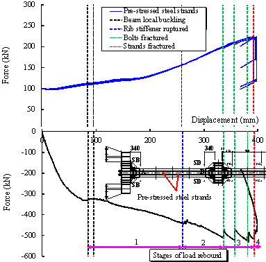
Figure 21 Axial force of pre-stressed steel strands and stages of load rebound of
Specimen M-P100-C
|
|

|
|
(a)
Local buckling
occurred on the upper flange in Section SD (1, D =
85 mm, F = 332 kN)
|
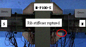
(b)
Upper south
rib stiffener in Section SA ruptured
(2, D = 260 mm, F = 443 kN)
|
|

|
|
|
(c)
Upper north
rib stiffeners in Sections SA and NA ruptured (3, D = 270 mm, F = 442 kN)
|
(d)
Upper bolt in
Section SA fractured
(4, D = 336 mm, F = 510 kN)
|
|
|
|
|
(e)
Another upper
bolt in Section SA fractured
(5, D = 357 mm, F = 520 kN)
|
(f)
Upper bolt in
Section NA fractured
(6, D = 381 mm, F = 529 kN)
|
|
|
|
|
(g)
Steel wires
of strands fractured one by one
(7, D = 393 mm, F = 517 kN)
|
|
|
Figure 22
Typical phenomena of Specimen M-P100-C
|
In particular, when D = 85 mm (Point 1 on Figure 20), the steel beam experienced
a local buckling on its upper flange at Section SD of the beam (see Figure
18). The external load of Specimen M-P100-C merely decreased from 332 kN to
321 kN. When 85 mm ˇÜ D < 260 mm, Specimen M-P100-C
was in Stage 1 of load rebound (Figure 21). Note that Stage 1 represents the transition stage
of the component from the compressive arch action
[50, 51] (Figure 17) to the catenary action [53-55].
Because of the local buckling
of the beam under the compressive arch action, the contribution of Specimen
M-P100-C to the load resistance decreased. However, such a contribution provided
by the steel strands due to the catenary action increased, which can be concluded
from Figure 21. Additionally, Lu et al. [34] found that the energy-dissipating
components can provide a steadily increasing load resistance. Therefore, the
external load in Stage 1 of load rebound firstly decreased and then increased.
Referring to Figure 22b, despite the fact that the upper south rib
stiffener in Section SA (Figure 18) ruptured at D = 260 mm (Point 2 on Figure 20), the specimenˇŻs resistance
decreased slightly (from 443 kN to 430 kN) due to force redistributions occurring
within the beam-to-column joint. Similarly, (D = 270 mm) the upper north rib stiffeners in Sections SA and
NA ruptured (see Figure 22c) and the specimenˇŻs resistance further decreased
(from 442 kN to 424 kN). When 260 mm ˇÜ D < 336 mm, Specimen M-P100-C
was in Stage 2 of load rebound (Figure 21). In this stage, the
steel strands (Figure 21) and the angle steels of the energy-dissipating
components can provide a steadily increasing resistance
[34]. Therefore, the external load declined for a short time and then continued to rise.
Notably,
due to the catenary action, the specimen was able to sustain more load up
to a vertical displacement D = 336 mm (Point 4 on Figure 20) and then one
of the upper bolts in Section SA fractured (see Figure 22d). Referring to
Figure 20, at this point, the specimenˇŻs resistance was instantaneously dropped
from 510 kN to 469 kN. However, the specimen was still able to redistribute
the load, albeit bolt fractures continued in the connections in Sections SA
(see Figure 22e) and NS (see Figure 22f). These are associated with Points
5 (D = 357 mm)
and 6 (D = 381 mm), respectively, in Figure 20. When 336 mm ˇÜ D < 393 mm, Specimen M-P100-C
was in Stage 3 of load rebound (Figure 21). It can be seen from Figure 21
that the fracture of the bolts had little influence on the steel strands.
The steel strands were still able to provide a steadily increasing resistance,
and served to provide the catenary action ensuring the stability of the structural
strength. Therefore, the external load
rebounded in this stage.
Finally,
the specimen lost its load carrying capacity at D = 393 mm because of consecutively fractured
steel tendons in the pre-stressed steel strands. This is shown in Figure 22g.
When 393 mm ˇÜ D < 399 mm, Specimen M-P100-C
was in Stage 4 of load rebound (Figure 21). When one of the strands was
broken, the remaining unbroken strands were not affected and could still provide
a steadily increasing resistance (Figure 21). With the increase of the beam-to-column
connection angle, the vertical force provided by the steel strands would increase.
Therefore, the external load
also rebounded in this stage.
In order to ensure the safety of the test, the test was terminated at D = 399 mm.
According to the DoD guidelines [40], Specimen
B-C complies with the case of welded unreinforced flange-bolted web (WUF-B).
The failure plastic rotation angle
a and the ultimate plastic rotation angle b of Specimen B-C
can be obtained by subtracting the yield rotation angle (0.0062 rad determined
by the DoD guidelines [40]) from the angles of the different critical states.
The failure plastic rotation angle a of Specimen B-C was 0.078 rad and the ultimate plastic rotation angle b of Specimen
B-C was larger than 0.083 rad, which are much
larger than the limits specified in the DoD guidelines [41] (a
= 0.016 rad, b = 0.043 rad). The deformation capacity and strength of Specimen M-P100-C are significantly
better than those of Specimen B-C, i.e., the rotational ductility of Specimen
M-P100-C was 59.6% higher than that of Specimen B-C and the strength of Specimen
M-P100-C was 22.6% higher than that of Specimen B-C. In conclusion, SPCRCF
has remarkably larger progressive collapse resistance.
4.2.2 Description of failure mechanism
This section intends to describe key findings
associated with differences in the failure mechanisms observed in Specimens
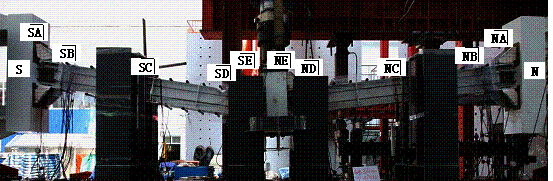
B-C and M-P100-C. For this reason, measurements from strain gauges installed
in characteristic cross-sections are fully correlated with the measured force-displacement
relationships of the specimens. Note that above a certain strain threshold,
the strain gauge measurements are only indicative of the load redistributions
occurring within the specimen.
(A) Specimen
B-C
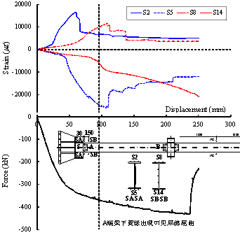
Figure 23 shows the engineering strain development
at four different locations (S2, S5, S8 S14), in the longitudinal direction
in Sections SA and SB of the steel beam. From this figure it is apparent that
during loading the upper beam flange in Sections SA and SB was always in tension while the
beamˇŻs lower flange was always in compression, as expected. Local buckling
occurred on the compression flange when D = 91 mm, thereby releasing the compressive arch
action. Thus, there was a slight decrease in the measured strains of the beam
flange (S2, S5, and S8). Strain S14 increased after beam flange local buckling
occurred because Section SB was located within buckled region. Note that measurements
after 3000 ¦Ě¦Ĺ are only indicative and depict the force re-distributions.
Similar observations hold true from measurements within Sections SD, SE, NA,
NB, ND, and NE of the B-C specimen. The measurements also confirm that after
fracture of the lower flange and the shear panel (Section SE), the CFST columns
remained elastic.
|
|
|
Figure 23
Strain development of the flange in Sections SA and SB (Specimen B-C)
|
|

|
|
Figure 24
Strain development of the flange in Sections SB and SD (Specimen M-P100-C)
|
(B) Specimen
M-P100-C
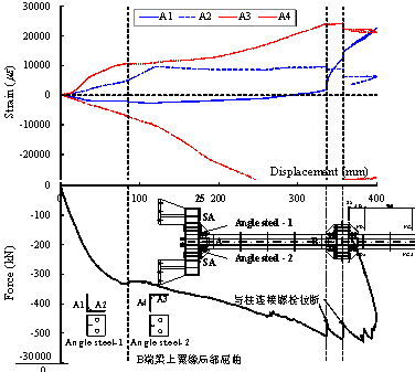
Figure 24 shows the progression of the engineering
strains extracted from nominally identical cross-sections (Sections SB and
SD) with Specimen B-C. In the same figure, the strain measurements are synchronized
with the applied load at Specimen M-P100-C. From this figure, the top beam
flange stayed always in tension, while the lower beam flange stayed always
in compression, thereby experiencing local buckling in Section SD at D = 85 mm. After that, the compressive arch action was released.
Local buckling caused load redistribution within the subassembly, which resulted
in a slight strain decrease of the flange in Section SD based
on the measured strains from S20 and S26. Because the local buckling was mainly
located in Section SD, the strain of the flange in Section SB changes more
smoothly.
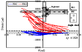
Referring to Figure 25, supplemental strain measurements
were conducted in this case at a cross-section (noted as Section SA) of the
angle steel. Four locations were monitored (noted as A1, A2, A3 and A4), which
are also shown in the same figure. During the loading process, the strains were always
compressive at locations A1 and A3, as expected. Similarly, the strain measurements
at locations A2 and A4 were tensile due to the flexural-tensile deformation
of the angle steel. From Figure 25, while the vertical displacement
increased, Strain A1 gradually switched from compression to tension. After
the fracture of the bolt occurred in Angle steel-1, the lever arm on the column leg of Angle steel-1 increased, thereby causing larger
tensile strains at location A1.
|
|
|
Figure 25
Strain development of the angle steel in Section SA (Specimen M-P100-C)
|
5.
Numerical simulation
Based on the experimental data, the finite
element models of Specimens B-S, M-P100-S, B-C, and M-P100-C were developed
using the general-purpose nonlinear finite element software, MSC.Marc [33].
All the components were modeled using solid
elements. Considering that there was no yield in the CFST column, elastic
material was adopted to model the column. Contact algorithm was adopted among
different components of the finite element models, which was consistent with
the actual situation. The pre-stressed forces in the bolts and strands were
modeled by the temperature stress. The initial geometric imperfections of
the beams and the rib stiffeners were simulated using the method proposed
in Eurocode 3 [56] and GB 50017-2017 [40]. The components gradually failed
during the tests, which could be simulated using the elemental deactivation
technique. The UACTIVE subroutine of MSC.Marc 2007 was adopted to deactivate
the element when its strain reached the material failure strain [57].
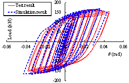
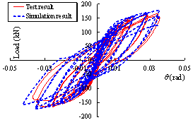
5.1 Seismic cyclic test specimens
The finite element models of Specimens B-S
and M-P100-S are shown in Figure 26. The comparisons between the simulation
and test results are shown in Figure 27. The comparisons show that the finite
element models established based on the above method can accurately simulate
the response of the specimens under cyclic loading.
|
|
|
|
(a)
B-S
|
(b)
M-P100-S
|
|
Figure 26 Finite element models of seismic cyclic test specimens
(1/4 model adopted due to symmetry)
|
|
|
|
|
(a)
B-S
|
(b)
M-P100-S
|
|
Figure 27
Comparisons between simulation and test results of seismic cyclic
test specimens
|
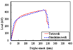
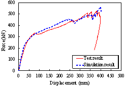
5.2 Progressive collapse test specimens
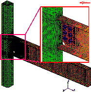
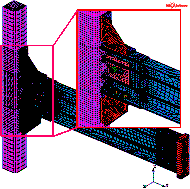
The comparisons between the simulation and
test results of Specimens B-C and M-P100-C are
shown in Figure 28. The comparisons show that the finite element models established
based on the above method can accurately simulate the progressive collapse
response of the structures under the middle column-removal scenario.
|
|
|
|
(c)
B-C
|
(d)
M-P100-C
|
|
Figure
28 Comparisons between simulation and test results
of progressive collapse test specimens
|
6. Conclusions
Comprehensive defense of seismic action and progressive collapse is a new frontier
for civil engineering practice. To improve the seismic and progressive collapse
resistant performance of a steel-concrete composite frame structure, an SPCRCF
was proposed in this work. Seismic and progressive collapse performances of
the conventional frame and the proposed SPCRCF were compared through experiments,
and the test specimens were simulated using general-purpose finite element
software. The following conclusions are drawn from this work.
(1) The initial stiffness
and strength of the proposed SPCRCF (Specimen M-P100-S) under cyclic loading
were similar to those of the conventional frame (Specimen B-S). In addition,
Specimen M-P100-S demonstrated less damage and smaller residual deformation
compared with Specimen B-S. Therefore, the proposed SPCRCF exhibited significantly
better seismic resilience.
(2) In the middle column-removal
scenario, the proposed SPCRCF (Specimen M-P100-C) exhibited the catenary action,
provided a better resistance and achieved a larger rotational capacity at
the beam-column connection, leading to enhanced deformation capacity and resistance,
as well as a higher safety margin compared with the conventional frame (Specimen
B-C). Therefore, the proposed SPCRCF yielded better progressive collapse performance.
(3) The finite element models
proposed in this work simulated the load-displacement responses accurately
under both earthquake ground motions and a middle column-removal scenario.
In summary, the proposed SPCRCF is proven
to have more seismic resilience and higher progressive collapse resistance
than the conventional steel-concrete composite frame.
Acknowledgement
This work was supported by Beijing Natural
Science Foundation [8182025]. The authors also thank Prof. Dimitrios Lignos
of EPFL for his constructive suggestions on this paper.
References
[1]
Nethercot D, Vidalis C. Improving the resistance
to progressive collapse of steel and composite moment frames. Structures Congress
2015; pp. 1138-1149. https://doi.org/10.1061/9780784479117.097.
[2]
Adaros MS, Smilowitz R. Challenges and considerations
for the retrofit of existing structures for progressive collapse. Journal
of Performance of Constructed Facilities 2014; 29(5):B4014001.
https://doi.org/10.1061/(ASCE)CF.1943-5509.0000675.
[3]
Hajjar JF. Composite steel and concrete structural
systems for seismic engineering. Steel Construction 2008; 58(5):703-723. https://doi.org/10.1016/S0143-974X(01)00093-1.
[4]
Mehanny SSF, Deierlein GG. Seismic damage
and collapse assessment of composite moment frames. Journal of Structural
Engineering 2001; 127(9):1045-1053. https://doi.org/10.1061/(ASCE)0733-9445(2001)127:9(1045).
[5]
Hajjar JF, Leon RT, Gustafson MA, Shield CK.
Seismic response of composite moment-resisting connections. II: behavior.
Journal of Structural Engineering 1998; 124(8):868-876. https://doi.org/10.1061/(ASCE)0733-9445(1998)124:8(877).
[6]
Ministry of Housing and Urban-Rural Development
of the People's Republic of China (MOHURD). Code for design of composite structures
(JGJ 138-2016). Beijing: China Architecture & Building Press; 2016. (in
Chinese).
[7]
China Association for Engineering Construction
Standardization (CECS). Code for anti-collapse design of building structures.
Beijing: China Planning Press; 2014. (in Chinese).
[8]
National Institute of Standards and Technology
(NIST). Evaluation of the FEMA P-695 methodology for quantification of building
seismic performance factors. National Institute of Standards and Technology,
Gaithersburg, Maryland; 2010.
[9]
British Standard Institute (BSI). BS EN 1994-1-1.
2004 Eurocode 4: Design of composite steel and concrete structures, Part 1-1:
general rules and rules for buildings. CEN Central Secretariat, Rue de Stassart
36, B-1050; 2004.
[10] Fascetti A, Kunnath SK, and Nistic¨° N. Robustness
evaluation of RC frame buildings to progressive collapse. Engineering Structures
2015; 86:242-249. https://doi.org/10.1016/j.engstruct.2015.01.008.
[11]
Khalili-Tehrani
P, Masroor A, Dogruel S, Cormie D, Gallo M, Almufti. Lessons learned from the design of steel
and RC structures against progressive collapse using nonlinear alternate path
analysis. Structures Congress 2014; pp. 954-965. https://doi.org/10.1061/9780784413357.085.
[12] Li Y, Ahuja A, Padgett JE. Review
of methods to assess, design for, and mitigate multiple hazards. Journal of
Performance of Constructed Facilities 2011; 26(1):104-117. https://doi.org/10.1061/(ASCE)CF.1943-5509.0000279.
[13] Lin KQ, Li Y, Lu XZ, Guan H. Effects of seismic
and progressive collapse designs on the vulnerability of RC frame structures.
Journal of Performance of Constructed Facilities 2016; 31(1):04016079. https://doi.org/10.1061/(ASCE)CF.1943-5509.0000942.
[14]
Lopez-Barraza A, Ruiz SE, Reyes-Salazar A,
Boj¨®rquez E. Demands and distribution of hysteretic energy in moment resistant
self-centering steel frames. Steel & Composite Structures 2016; 20(5):1155-1171.
http://dx.doi.org/10.12989/scs.2016.20.5.1155.
[15]
Rojas P, Ricles JM, Sause R. Seismic performance
of post-tensioned steel moment resisting frames with friction devices. Journal
of Structural Engineering 2005; 131(4):529-540. https://doi.org/10.1061/(ASCE)0733-9445(2005)131:4(529).
[16] Christopoulos C, Filiatrault
A, Uang CM, Folz B. Posttensioned
energy dissipating connections for moment-resisting steel frames. Journal
of Structural Engineering 2002; 128(9):1111-1120. https://doi.org/10.1061/(ASCE)0733-9445(2002)128:9(1111).
[17] Garlock MM, Ricles JM, Sause R. Influence
of design parameters on seismic response of post-tensioned steel MRF systems.
Engineering Structures 2008; 30(4):1037-1047. https://doi.org/10.1016/j.engstruct.2007.05.026.
[18] Ricles JM, Sause R, Peng SW, Lu LW. Experimental
evaluation of earthquake resistant posttensioned steel connections. Journal
of Structural Engineering 2002; 7(7):850-859. https://doi.org/10.1061/(ASCE)0733-9445.
[19] Wang W, Fang C, Liu
J. Self-centering beam-to-column connections with combined superplastic
SMA bolts and steel angles. Journal of Structural Engineering 2016; 143(2):04016175.
https://doi.org/10.1061/(ASCE)ST.1943-541X.0001675.
[20] Wang W, Chan TM, Shao
HL, Chen YY. Cyclic behavior of connections equipped
with NiTi shape memory alloy and steel tendons between H-shaped beam to CHS
column. Engineering Structures 2015; 88:37-50. https://doi.org/10.1016/j.engstruct.2015.01.028.
[21]
Kim HJ, Christopoulos C. Friction damped posttensioned self-centering
steel moment-resisting frames. Journal of Structural Engineering 2008;
134(11):1768-1779. https://doi.org/10.1061/(ASCE)0733-9445(2008)134:11(1768).
[22]
Zhang AL, Zhang YX, Li R, Wang ZY. Cyclic behavior of a prefabricated
self-centering beam¨Ccolumn connection with a bolted web friction device.
Engineering Structures 2016; 111:185-198. https://doi.org/10.1016/j.engstruct.2015.12.025.
[23]
Guo T, Song LL, Zhang GD. Numerical simulation and seismic fragility analysis of self-centering
steel MRF with web friction devices. Journal of Earthquake Engineering
2015; 19(5):731-751. https://doi.org/10.1080/13632469.2014.1003437.
[24] Eatherton MR, Ma X,
Krawinkler H, Mar D, Billington S, Hajjar JF, Deierlein GG. Design concepts for controlled rocking of self-centering steel-braced
frames. Journal of Structural Engineering 2014; 140(11):04014082. https://doi.org/10.1061/(ASCE)ST.1943-541X.0001047.
[25] Vasdavellis G, Baiguera M, AI-Sammaraie D.
Numerical simulation of the progressive collapse behaviour of steel self-centering
moment resisting frames. 8th International Conference on Steel and Aluminium
Structures, Hong Kong, China; 2016.
[26] Pirmoz A, Liu M. Finite element modeling and
capacity analysis of post-tensioned steel frames against progressive collapse.
Engineering Structures 2016; 126:446-456. https://doi.org/10.1016/j.engstruct.2016.08.005.
[27] Rousakis TC, Panagiotakis GD, Archontaki EE,
Kostopoulos AK. Prismatic RC columns externally confined with FRP sheets and
pretensioned basalt fiber ropes under cyclic axial load. Composites Part B:
Engineering 2019; 163:96-106. https://doi.org/10.1016/j.compositesb.2018.11.024.
[28] Rousakis TC. Inherent seismic resilience of
RC columns externally confined with nonbonded composite ropes. Composites
Part B: Engineering 2018; 135:142-148. https://doi.org/10.1016/j.compositesb.2017.10.023.
[29] Rousakis TC. Hybrid confinement of concrete
by fiber-reinforced polymer sheets and fiber ropes under cyclic axial compressive
loading. ASCE, Journal of Composites for Construction 2013; 17(5):732-43. https://doi.org/10.1061/(ASCE)CC.1943-5614.0000374.
[30] Fakharifar M, Chen G, Sneed L, Dalvand A.
Seismic performance of post-mainshock FRP/steel repaired RC bridge columns
subjected to aftershocks. Composites Part B: Engineering 2015; 72:183-198.
https://doi.org/10.1016/j.compositesb.2014.12.010.
[31] Kwon M, Seo H, Kim J. Seismic performance
of RC-column wrapped with Velcro. Structural Engineering & Mechanics 2016;
58(2):379-395. https://doi.org/10.12989/sem.2016.58.2.379.
[32] Echevarria A, Zaghi AE, Christenson R, Accorsi
M. CFFT bridge columns for multihazard resilience. Journal of Structural Engineering
2016; 142(8):C4015002. https://doi.org/10.1061/(ASCE)ST.1943-541X.0001292.
[33] MSC. Software Corp. MSC. Marc userˇŻs manual.
MSC. Software Corporation, Santa Ana, CA; 2007.
[34] Lu XZ, Zhang L, Cui Y, Li Y, Ye LP. Experimental
and theoretical study on a novel dual-functional replaceable stiffening angle
steel component. Soil Dynamics and Earthquake Engineering 2018; 114:378-391. https://doi.org/10.1016/j.soildyn.2018.07.040.
[35]
Yang XM, Xu HC, Zhen W, Bao LJ. Structural
seismic design of Luoyang Zhengda ultra-limit high-rise office building. Building
Structure 2013; 18:39-43. (in Chinese). https://doi.org/10.19701/j.jzjg.2013.18.008.
[36] Ministry of Housing and Urban-Rural Development
of the People's Republic of China (MOHURD). Code for seismic design of buildings
(GB50011-2010). Beijing: China Architecture & Building Press; 2010. (in
Chinese).
[37] Lu XZ, Li MK, Guan H, Lu X, Ye LP. A comparative
case study on seismic design of tall RC frame-core tube structures in China
and USA. The Structural Design of Tall and Special Buildings 2015; 24:687-702.
10. https://doi.org/10.1002/tal.1206.
[38] American Society of Civil Engineers (ASCE).
Minimum design loads and associated criteria for buildings and other structures,
ASCE/SEI 7-16, Reston, VA; 2016.
[39] American Institute of Steel Construction (AISC). Seismic provisions for structural
steel buildings. ANSI/AISC 341-16, Chicago; 2016.
[40] Ministry of Housing and Urban-Rural Development
of the People's Republic of China (MOHURD). Standard for classification of
steel structures (GB 50017-2017). Beijing: China Architecture & Building
Press; 2017. (in Chinese).
[41] Department of Defense (DoD). Design of structures
to resist progressive collapse. Unified facility criteria, UFC 4-023-03, Washington,
DC; 2016.
[42] Zhang AL, Zhang YX, Li R, Wang ZY. Cyclic
behavior of a prefabricated self-centering beam-column connection with a bolted
web friction device. Engineering Structures 2016; 111:185-198. https://doi.org/10.1016/j.engstruct.2015.12.025.
[43] Standardization Administration of the PeopleˇŻs
Republic of China (SAC). Metallic materials - Tensile testing - Part l: Method
of test at room temperature (GB/T 228.1 - 2010). Beijing: China Zhijian Publishing
House; 2010. (in Chinese).
[44] Ministry of Housing and Urban-Rural Development
of the People's Republic of China (MOHURD). Technical specification for concrete
structures prestressed with unbonded tendons (JGJ 92-2016). Beijing: China
Architecture & Building Press; 2016. (in Chinese).
[45] American Concrete Institute (ACI). 550.3-13.
Design specification for unbonded post tensioned precast concrete special
moment frames satisfying ACI 374.1 and commentary, Farmington Hills, MI; 2013.
[46] Mattock AH. Flexural strength of prestressed
concrete sections by programmable calculator. PCI Journal 1979; 885-886.
https://doi.org/10.15554/pcij.01011979.32.54.
[47] Federal Emergency Management Agency (FEMA).
Seismic performance assessment of buildings volume 1-methodology, FEMA P-58.
Federal Emergency Management Agency, Washington, DC; 2012.
[48] Lignos DG, Krawinkler H. Development and utilization
of structural component databases for performance-based earthquake engineering.
Journal of Structural Engineering 2013; 139(8):1382-1394. https://doi.org/10.1061/(ASCE)ST.1943-541X.0000646.
[49] Lignos DG, Krawinkler H. Deterioration modeling
of steel components in support of collapse prediction of steel moment frames
under earthquake loading. Journal of Structural Engineering 2011; 137(11):1291-1302.
https://doi.org/10.1061/(ASCE)0733-9445(2002)128:4(420).
[50] Lu XZ, Lin KQ, Li CF, Li Y. New analytical calculation
models for compressive arch action in reinforced concrete structures. Engineering
Structures 2018; 168:721-735. https://doi.org/10.1016/j.engstruct.2018.04.097.
[51] Kang SB, Tan KH. Analytical model for compressive
arch action in horizontally restrained beam-column subassemblages. ACI Structural
Journal 2016; 113(4):813-826. https://doi.org/10.14359/51688629.
[52] Ling L, Wei W, Chen Y, Lu Y. Effect of beam
web bolt arrangement on catenary behaviour of moment connections. Steel Construction
2015; 104(104):22-36. https://doi.org/10.1016/j.jcsr.2014.09.016.
[53]
Li Y, Lu XZ, Guan
H, Ye LP. Progressive collapse resistance demand of RC frames under catenary
mechanism. ACI Structural Journal
2014; 111(5):1225-1234. https://doi.org/10.14359/51686809.
[54] Li Y, Lu XZ, Guan H, Ye LP. An
improved tie force method for progressive collapse resistance design of reinforced
concrete frame structures. Engineering Structures 2011; 33(10):2931-2942.
https://doi.org/10.1016/j.engstruct.2011.06.017.
[55] Guo LH, Gao S, Fu F, Wang YY. Experimental study
and numerical analysis of progressive collapse resistance of composite frames.
Journal of Constructional Steel Research 2013; 89(5):236-251.
https://doi.org/10.1016/j.jcsr.2013.07.006.
[56] British Standard Institute (BSI). BS EN 1993-1-1.
2005 Eurocode 3: Design of steel structures, Part 1-1: general rules and rules
for buildings. CEN Central Secretariat, Rue de Stassart 36, B-1050; 2005.
[57]
Lu X, Lu XZ, Guan H, Ye LP, Collapse simulation
of reinforced concrete high-rise building induced by extreme earthquakes.
Earthquake Engineering & Structural Dynamics 2013; 42(5):705-723. https://doi.org/10.1002/eqe.2240.
*
Corresponding author, Email: luxz@tsinghua.edu.cn
|