1. Introduction
Many modern cities are transforming into more sophisticated and integrated infrastructure systems, which significantly increases the risk of earthquake-induced damages in these cities. For example, the 2008 Wenchuan earthquake in China [1, 2] and the 2011 Christchurch earthquake in New Zealand [3] have led to massive loss of life and property. The resulting significant social, psychological and economic consequences have promoted the research in urban seismic damage simulation for improving emergency preparedness and mitigating possible earthquake-induced losses of high seismic regions and populous modern cities.
Hazus and MAEviz are widely used platforms for urban seismic simulation [4-6]. Both of these platforms are based on building inventory data. An inherent shortcoming of these platforms is that, the absence of the 3D geometric features of the buildings limits high-fidelity modeling of the geometric related dynamic properties of these buildings. For example, the proportion of the inter-story flexural deformation and shear deformation varies with the height/width ratio of the building, which results in different vibration mode shapes and natural frequencies [7, 8]. In addition, a vertically irregular plan layout may cause displacement concentration on floors with abrupt stiffness change. Therefore, without a proper consideration of the 3D geometric related dynamic properties of buildings, the seismic damage predictions may not be accurate and reliable.
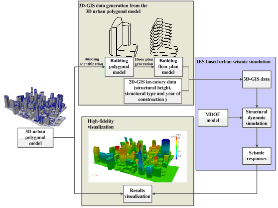
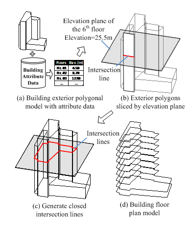
To better account for the dynamic properties in relation to the 3D geometric layout of buildings, Hori et al. [9] proposed the integrated earthquake simulation (IES) based on a 3D geographic information system (GIS). IES is able to perform the entire process of urban seismic simulation, including seismic ground motion generation, structural dynamic simulation and human/social response prediction. Accelerated by high-performance computing, IES has been adopted for the seismic simulation of Tokyo city [10]. In the simulation, 3D-GIS data are used as the input source, which contains all necessary geometric information (e.g., the floor plan on different elevations) and attribute information (e.g., structural height, structural type and year of construction) of buildings. Note that 3D-GIS data provide much more comprehensive information of buildings than the building inventory data. Note also that different computational models (e.g., multi-degree-of-freedom (MDOF) model and non-linear Distinct Element Method (DEM) [11]) are supported by IES thus making a full utilization of the available building information. Using the 3D-GIS data together with the IES-based urban seismic simulation can better predict the dynamic properties of individual buildings having irregular vertical and horizontal layouts.
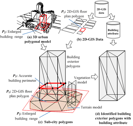
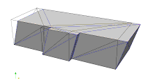
To date, however, limited 3D-GIS data can be utilized directly by IES. Due to security or confidentiality concerns, large amount of 3D-GIS data administrated by city governments or commercial companies are not publicly accessible. Even available, much of these 3D-GIS data adopt a 3D polygonal model or a solid model to represent the building geometric information [12, 13], which cannot provide the floor plan data that are required by IES. Furthermore, much of the available 3D-GIS data are in reality 2.5D data, which are extruded from the 2D-GIS plan layout polygons according to the building heights, as shown in Figure 1. Such 2.5D data cannot correctly represent the buildings that are vertically irregular. Thus, a methodology to generate the 3D-GIS data from the more accessible 3D city data is needed.
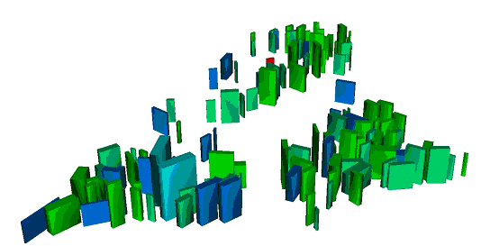
Figure 1. 2.5D data of Shantou, China
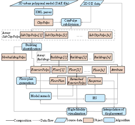
With rapid advances in light detection and ranging (LiDAR) together with photogrammetry technology [14, 15], 3D urban polygonal models of cities can be generated automatically or semi-automatically. Indeed, an increasing numbers of urban areas have accessible 3D urban polygonal models [16-19]. For example, Google provides global metropolises with realistic 3D models, as shown in Figure 2. Similarly, CyberCity3D provides 3D models for 62 cities in the United States (US) [19]. A 3D urban polygonal model contains comprehensive urban geometric information and has a wide range of applications in urban visualization and urban environment simulation (e.g., the application of city smoke propagation simulation [20]). In addition, high level of accuracy of the 3D urban polygonal model makes it viable to generate the 3D-GIS data [21]. For this reason, the 3D urban polygonal model is adopted in this study as the data source for the IES-based urban seismic simulation. Note that having two major differences from the 3D-GIS data required by IES, the 3D urban polygonal model (1) contains no descriptive information of each building (e.g., structural height, structural type and year of construction, etc.), such information is highly critical to estimate the dynamic properties of a structure; (2) is formed by building exterior polygons, whereas IES requires the floor plan as the input of the building geometric information, therefore, the 3D urban polygonal model cannot be used directly for the IES-based urban seismic simulation. In view of the limitations of the 3D urban polygonal model and given that the widely available urban 2D-GIS data can provide comprehensive building attribute information, a data conversion processes are thus proposed in this work to integrate the urban 2D-GIS data and the 3D urban polygonal model to generate the 3D-GIS data required for the IES-based urban building seismic simulation.
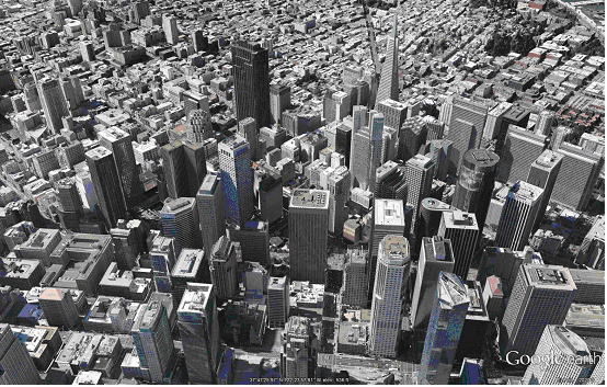
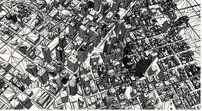
Figure 2. Google Earth 3D urban polygonal model
In addition to the structural dynamic simulation, the visualization of urban earthquake disaster scenario is also a very important component of any urban seismic simulation. A comprehensive visualization of urban building seismic responses can not only provide the government authorities and other stakeholders a better knowledge of the potential losses, but also offer a useful tool for disaster prevention training or disaster emergency preparedness planning [22-24].
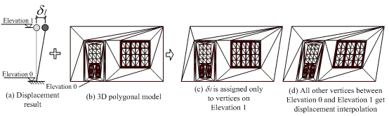
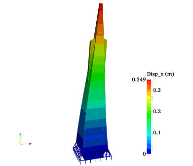
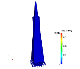
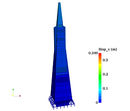
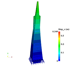
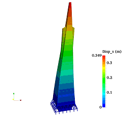
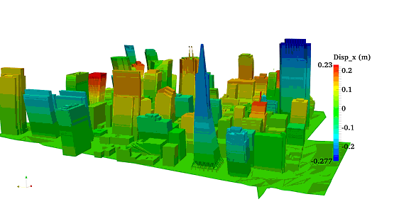
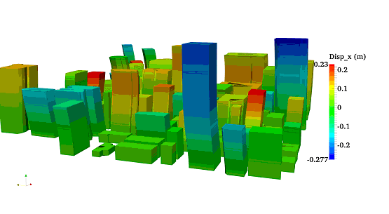
Despite of the calculation power of the IES-based urban seismic simulation, its computational models in general cannot be used directly to produce a high-fidelity visualization of the simulation. For example, when using the MDOF computational model, each building floor is represented by only a mass point, which is far from a realistic visualization. Conventionally, if the 3D-GIS data are not available, the 2.5D model that is generated by extruding the buildings from the floor plan polygons (Figure 1) will be used [25]. Obviously, such a 2.5D model is also far from the realistic façade. In addition, non-building objects, such as terrain, roads and vegetation, are neglected in the visualization. Hence, current seismic visualization methods have much room for improvement.
In contrast to the 2.5D model, the 3D urban polygonal model featured with rich architectural details can provide a realistic visualization for building as well as non-building objects. As a result, the 3D urban polygonal model is used herein to visualize the urban building seismic responses with high-fidelity of urban earthquake disaster scenario. In this work, deformations of buildings predicted by IES will be mapped to the 3D urban polygonal model to generate high-fidelity and realistic visualizations of the seismic response. In addition, both building and non-building objects of the original 3D urban polygonal model will be visualized to make the visualization more realistic.