Experimental Investigation of Progressive Collapse Resistance of One-Way Reinforced Concrete Beam-Slab Substructures under a Middle-Column-Removal Scenario

Peiqi Ren a,b, Yi Li a, Xinzheng Lu b,*, Hong Guan c, Yulong Zhou b

a Key Laboratory of Urban Security and Disaster Engineering of Ministry of Education, Beijing Collaborative Innovation Center for Metropolitan Transportation, Beijing University of Technology, Beijing 100124, China.

b Key Laboratory of Civil Engineering Safety and Durability of Ministry of Education, Tsinghua University, Beijing 100084, China.

c Griffith School of Engineering, Griffith University Gold Coast Campus, Queensland 4222, Australia.

Engineering Structures, 2016, 118: 28-40.

Download Full Text PDF

Download Test Data Excel File

Abstract

Floor systems composed of beams and slabs are critical structural elements of frame structures to resist progressive collapse. Previous experimental studies have focused mainly on beam-column or continuous-beam substructures and have ignored the influence of the slab. To study the progressive collapse-resisting mechanisms of reinforced concrete (RC) floor systems, seven 1/3-scaled one-way substructure specimens, including five beam-slab specimens and two continuous-beam specimens without slabs, were tested under a middle-column-removal scenario. The effects of various structural parameters, including sectional dimensions (beam height, slab width, and slab thickness) and seismic reinforcement, on the progressive collapse resistance were studied by analyzing material strains and load-displacement curves. Under small deformations, the progressive collapse resistance was largely affected by the beam height, slab width and seismic reinforcement in the beams. However, the effect of the slab width, upon exceeding the effective flange width, became insignificant. Note that increasing the slab thickness simultaneously increased the amount of slab reinforcement according to the minimum requirement of reinforcement ratio for slabs, such an increase will in turn enhanced the progressive collapse resistance. In addition, the existence of the slab led to an over-reinforced damage in the compressive zones of the beam ends, which accelerated the bending failure and the presence of the catenary action of the specimens. Under large deformations, the progressive collapse resistance was mainly influenced by the reinforcement area of the entire beam-slab section. The total reinforcement area of a beam-slab substructure designed to meet a higher seismic requirement was not significantly increased, and consequently, the progressive collapse resistance of the substructure under the catenary mechanism was not notably improved. This finding stands in stark contrast to those of previous tests of beam-column specimens without slabs.

Keywords: Reinforced concrete frame structure, one-way beam-slab substructure, progressive collapse resistance, middle column removal scenario, experimental investigation

DOI: 10.1016/j.engstruct.2016.03.051

If you need the PDF version of this paper, please email to luxinzheng@sina.com

1. Introduction

The progressive collapse of a building structure is defined as a disproportionate or overall structural collapse caused by an initial local failure which propagates in the structural system [1]. Progressive collapse not only results in casualties and property damage but also has significant social, psychological and economic consequences. As such, how to minimize the risk of progressive collapse has increasingly attracted worldwide attention. Several design methods for improving the progressive collapse resistance of building structures have also been proposed by various design codes [1-3] and special guidelines [4-5].

The progressive collapse-resisting performance of reinforced concrete (RC) frames has been theoretically investigated in three major aspects. Izzuddin et al. [6], Xu and Ellingwood [7] and Li et al. [8] have proposed various design methods. Li et al. [9,10] and Tsai and Lin [11] have examined the dynamic effect associated with the progressive collapse. Brunesi et al. [12] and Fascetti et al. [13] proposed the theoretical methods to assess the progressive collapse resistance of RC framed structures. Numerical simulations have been also conducted to investigate the progressive collapse resistance of RC beams [14] and frames [15]. In addition, many researchers have studied collapse mechanisms using experimental means. A recent experimental study by Qian et al. [16] has revealed that RC frames exhibit different progressive collapse-resisting mechanisms under different deformation states: for small deformations, the collapse resistance is provided by the flexural capacity at the beam ends and the compressive arch action (CAA) within the beams themselves; whereas for large deformations, the resistance is provided by the so-called catenary action through the tensile force in the beams.

It should be noted that previous experimental investigations [17-21] have mainly focused on beam-column subassemblies and have mostly neglected the effect of slabs on the progressive collapse-resisting performance of frames. In real structures, however, RC slabs play an important role in redistributing unbalanced loads and bridging initial local failures. This is because slabs are cast monolithically with beams and act as horizontal members in transferring the unbalanced gravity loads induced by the initial local failure of the column.

Qian and Li [22] conducted a series of static collapse tests on beam-slab substructures under a corner-column-removal scenario. In their work, the contribution of the slab to progressive collapse resistance was analyzed by comparing the beam-slab substructures with beam specimens. Their test results indicated that the risk of collapse can be significantly reduced by the slab contribution. Qian and Li [23] also performed dynamic collapse tests on beam-slab substructures in the corner areas of RC frames, in which the effect of slabs during the dynamic collapse process was studied through comparison with the results of their static tests [22]. In an experimental study conducted by Pham and Tan [24], the beam-slab substructures were subjected to a penultimate internal column loss under a uniform load. The collapse mechanism of the substructures and the impact of the aspect ratio and the amount of slab reinforcement on the failure mode were studied. Gouverneur et al. [25] tested a restrained RC slab strip exposed to a simulated accidental failure of a central support and found that the collapse resistance was significantly increased by the tensile membrane action of the slab.

The outcomes of the experimental studies mentioned above indicate that slab contribution to the collapse resistance is significant. This is because, in addition to the CAA and the one-dimensional catenary action of beams, slabs are able to develop two-dimensional (2-D) compressive membrane action (CMA) under small deformations and 2-D tensile membrane action (TMA) under large deformations. These 2-D actions are thought to provide additional progressive collapse resistance. Although many researchers have studied CMA [26] and TMA [27,28] in slabs, and some [29] have considered the influence of TMA on collapse resistance, an in-depth and systemic study in this area is still needed. In particular, emphasis should be given to the beam-slab interaction in resisting collapse under different deformation scenarios and the influence of various structural parameters on the collapse resistance.

In this work, a series of experimental tests were performed to investigate the collapse mechanism and resistance of RC beam-slab substructures. Given the complicated spatial mechanical behavior of slabs, a one-way beam-slab substructure was considered and its one-dimensional mechanical behavior was examined. A total of seven 1/3-scaled specimens were tested in response to the failure of a middle column. These specimens include five one-way beam-slab substructures and two continuous-beam substructures. Various structural parameters to be considered were the sectional dimensions (i.e., beam height, slab thickness and slab width) and the seismic reinforcement. The failure modes of the substructures and the effects of the various structural parameters on the progressive collapse resistance of beam-slab substructures were examined systematically.

2. Experimental program

2.1 Design of the specimens

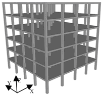
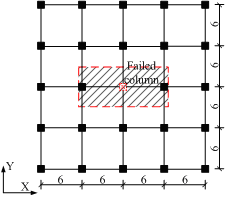
The prototype structure is a six-story RC frame (Figure 1) designed in accordance with the Chinese building codes [30,31]. The first story is 4.2 m in height, and the remaining stories are 3.6 m in height. The span length in both directions is 6 m. The design dead and live loads are 5.0 kN/m2 and 2.0 kN/m2, respectively. The beams and columns in the structure are designed to be ductile-bending-controlled while the shear and torsional failure can be prevented [30,31]. According to the code requirement [30,31], the beams and columns are expected to be damaged in bending in which the tension reinforcement yields while concrete in compression crushes, resulting in a large ductile rotational deformation. The beam-slab substructure being tested is highlighted with the shaded area enveloped by the red rectangle, as shown in Figure 1b. Due to the restraint of the laboratory space, the substructure was scaled down to 1/3. Published research confirmed that the critical scaling factor for RC specimens not damaging in shear is 1/4 which can well represent the resistance mechanisms and load-displacement relations of large scaled specimens [32]. Hence, 1/4 [16,24], 1/3 [17,21-23] and 1/2 [19,20] scales were adopted in many progressive collapse tests on RC substructures, in which the size effect on the collapse mechanism and resistance can be neglected [20,32]. The sectional dimensions of the prototype structure and the control specimen are given in Table 1. The thicknesses of the concrete cover of the beams and slabs of the test specimens were 6 mm and 5 mm, respectively.

Table 1 Sectional sizes of the prototype structure and the control specimen

Type

Column

Beam

Boundary beam

Prototype structure

600 mm × 600 mm

250 mm × 500 mm

Control specimen

200 mm × 200 mm

85 mm × 170 mm

500 mm × 370 mm

Figure 1 The prototype structure (units: m)

  Figure 1 The prototype structure (units: m)

(a) Perspective view

(b) Plan view

Figure 1 The prototype structure (units: m)

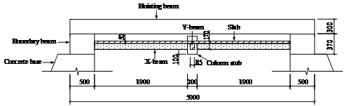
The tested area within the real structure was restrained along the perimeter edges by the surrounding slabs and beams. In the tests, the actual boundary condition was simplified as having two fixed sides in the x-direction and two free sides in the y-direction. This represented a one-way beam-slab substructure. Although, in reality, the slabs are restrained in both directions resulting in two-way CMA and TMA, one-way CMA and TMA being the basis of the two-way actions have not previously been studied systematically. Hence the one-way actions were investigated in this work to provide the fundamental understanding for further studies on the two-way actions. To reliably achieve the required one-way boundary condition, two strong boundary beams were designed to be part of the specimens (Figure 2). These boundary beams had a much larger sectional size than the structural beams. Therefore they had sufficient stiffness to restrain the translation and rotation of the specimen and provided adequate space in which the longitudinal reinforcement of the specimen could be well anchored. In addition, to facilitate the transportation and lifting of the specimens, two hoisting beams were cast monolithically with each specimen. The hoisting beams were able to support the weight of the specimens to avoid damage to the specimens during the transportation and lifting process. At the position of the removed column, a concrete stub (with a sectional dimension shown in Table 1) was designed to have a 100 mm extrusion from the beam soffit (Figure 2b).

Figure 2 Dimensions of the control specimen (units: mm)

(a) Plan view

Figure 2 Dimensions of the control specimen (units: mm)

(b) Elevation view

Figure 2 Dimensions of the control specimen (units: mm)

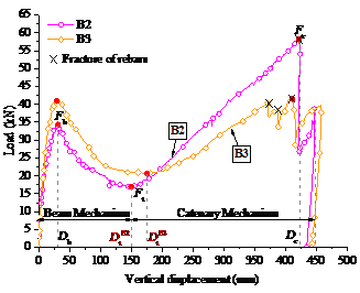
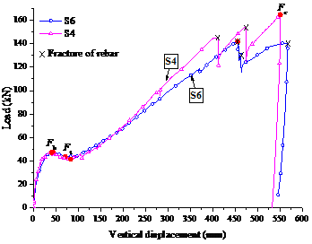
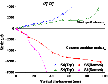
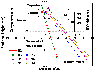
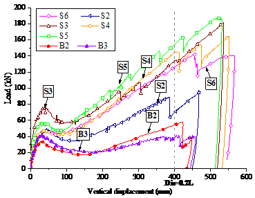
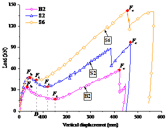
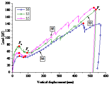
A total of seven specimens were designed to study the effects of various structural parameters on the collapse resistance. These included five beam-slab substructure specimens (referred to as the “S-series” and designated as S2 to S6) and two continuous-beam specimens without slabs (referred to as the “B-series” and designated as B2 and B3). The sectional sizes and the reinforcement details are given in Table 2 and Figure 3. The structural parameters considered were the slab thickness ts, the slab width ws, the beam height hb, and the seismic reinforcement. Specimens S6 and B2 were the control specimens for the S- and B-series, respectively. Their seismic design intensity was 6 degree, i.e., the peak ground acceleration (PGA) was 0.05 g for the design earthquake (with a 10% probability of exceedance in 50 years), where g was the acceleration of gravity. The other specimens differed from S6 (or B2) by altering only one parameter. For instance, the slab width of S2 was changed to the effective flange width as specified in the design code [30] (i.e., six times the slab thickness on each side of the beam), instead of 1 m on each side of the beam axis. S3 (B3) had a larger beam height of 200 mm, compared to the height of S6 (B2), which was 170 mm. S4 had a higher seismic design intensity of 8 degree (PGA = 0.20 g for the design earthquake), i.e. a higher level of earthquake demand, which resulted in a larger amount of seismic reinforcement for the beam (Table 2). S5 had a larger slab thickness of 75 mm. In consequence, to satisfy the requirement for the minimum reinforcement ratio of the slab specified in the design code [30], the amount of slab reinforcement in S5 was also increased (Table 2).

Table 2 Cross-sectional dimensions and reinforcement details (units: mm)

Specimen

Beam height

hb

Beam width

wb

Slab thickness

ts

Slab width

ws

Beam top

Beam bottom

Slab bottom

Slab top

Beam end

Mid-span

Longitudinal

/ Transverse

Longitudinal

/ Transverse

B2

170

85

2f8+1f6

2f8

2f8

B3

200

85

2f8+1f6

2f8

2f8

S2

170

85

50

685

2f8+1f6

2f8

2f8

f 6@190

f 6@190

S3

200

85

50

2000

2f8+1f6

2f8

2f8

f 6@190

f 6@190

S4

170

85

50

2000

3f10

2f10

2f10

f 6@190

f 6@190

S5

170

85

75

2000

2f8+1f6

2f8

2f8

f 6@160

f 6@160

S6

170

85

50

2000

2f8+1f6

2f8

2f8

f 6@190

f 6@190

(a) Reinforcement in the slab

(a) Reinforcement in the slab

(b) Reinforcement in the X-beam

(b) Reinforcement in the X-beam

(c) Reinforcement in the Y-beam

(d) Sectional view of the beam

(c) Reinforcement in the Y-beam

(d) Sectional view of the beam

Figure 3 Details of the reinforcement in S6 (units: mm)

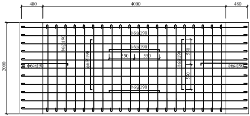
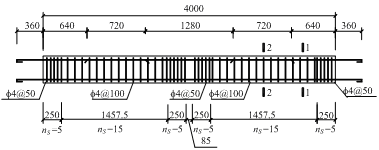
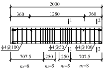
Note: ns is the number of steel hoops in the corresponding area.

The reinforcement ratios for the longitudinal tension reinforcements of B2, S2, S6 and S5, B3 and S3, and S4 were 1.0%, 0.8% and 1.7% respectively which were between the minimum and maximum ratios (i.e. 0.2% and 2.5%, respectively) regulated by the Chinese codes [30,31]. According to these codes [30,31], the amount of transverse reinforcement in beams is determined by the calculated seismic shear demand and detailing requirements of stirrup reinforcement. For the prototype structures with two different seismic safety levels (i.e. the seismic design intensities), the seismic shear demands are already satisfied when the stirrups meet the detailing requirements for the corresponding seismic safety levels. In other words, the amount of stirrups regulated by the detailing requirements specified in the codes [30,31] is related to the geometrical dimensions of the beams. This resulted in a similar amount of transverse reinforcement in the beams of the specimens. For example, the spaces of the stirrups in the plastic hinge region were supposed to be 48mm for B3 and S3 and 43mm for the other specimens respectively, according to the requirements in the Chinese codes [30,31]. The stirrup spacing in the other regions should be 150mm for S4 and 90mm for the other specimens, respectively [30]. Given that the diameter of immersion vibrators is approximately 50mm, to facilitate vibration of concrete, 50mm and 100mm were chosen in this work as the stirrup spacing in the plastic hinge regions and the other regions, respectively. As no shear failure was observed in the test, such a spacing was considered satisfactory. The reinforcement ratios for the stirrups inside and outside the plastic hinge regions were 0.6% and 0.3% respectively which were larger than the minimum ratio 0.24ft/fvy (i.e. 0.17%) regulated by the Chinses code [30], where ft was the tensile strength of the concrete and fvy was the yield strength of the stirrups.

2.2 Material properties

The specimens were made with C30-grade concrete, with an average compressive strength of 44 MPa, which was determined using the standard cubes with a size of 150 mm × 150 mm × 150 mm. The average yield strengths of the rebars with diameters of 4 mm, 6 mm, 8 mm, and 10 mm were 618 MPa, 387 MPa, 390 MPa, and 370 MPa, respectively, and the average ultimate strengths were 715 MPa, 475 MPa, 468 MPa, and 560 MPa, respectively.

2.3 Test setup and instrumentation

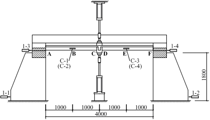
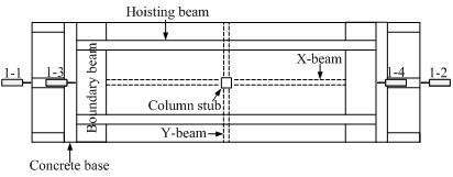
To achieve the fixed boundary condition at the two supports in the x-direction and provide enough space for large deformation of the specimens, two large concrete bases fixed on the strong ground floor were placed under the boundary beams (Figure 4). For each pair of the boundary beam and the connecting concrete base, two sets of two steel plates (the steel plate in the boundary beam was 500 mm × 160mm × 20mm whilst that in the concrete base was 500 mm × 230 mm × 35 mm) were embedded in the vicinity of their front and back surfaces (see Figure 4). When a specimen was placed on the two bases, an external steel plate with a dimension of 500 mm × 260 mm ×20 mm was welded and bolted, respectively, to the embedded plates in the boundary beam and the concrete base (Figure 4a). By doing so, fixed connections between the boundary beams and the concrete bases could be achieved. The linear variable differential transducers (LVDTs) that were installed at the boundary beams and at the concrete bases, shown as 1-1 through 1-4 in Figure 5, further confirmed the fixity of the boundary condition during the test.

(a) Front view

(a)    Front view

(b) Front perspective view

(c) Back perspective vie

(b)   Front perspective view

(c)    Back perspective view
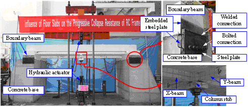
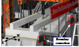
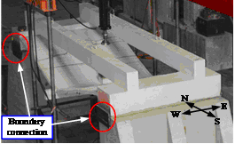
Figure 4 Test setup

Concentrated vertical loads were applied to each specimen at the position of the removed column using two hydraulic actuators, one above and the other below the specimen (Figure 4a). At the beginning of each test, a pair of small balanced forces (< 10 kN) was simultaneously applied by the two actuators. Afterwards, while the lower actuator maintained the small constant force, the upper actuator applied a gradually increased force. The displacement-controlled loading method was adopted in the test with a loading rate of 2 mm/minute and 4 mm/minute under the beam and caternary mechanisms, respectively. Thereby, a continuously increased deformation was applied to the specimens by which the structural resistance of the specimens at different deformation stages were obtained after the removal of a middle column. In addition, a stable loading process could also be achieved by this loading approach when the stiffness and strength of the specimens significantly deteriorated under large deformation.

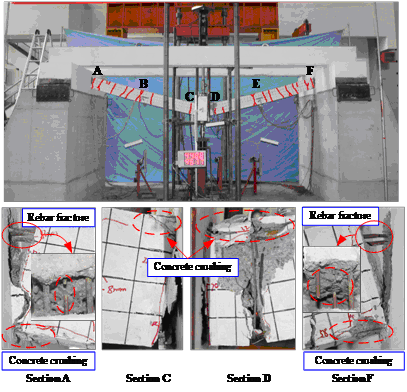
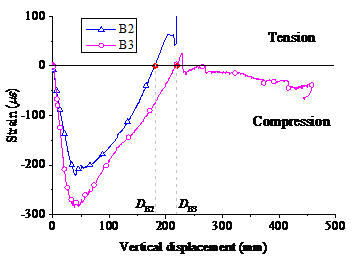
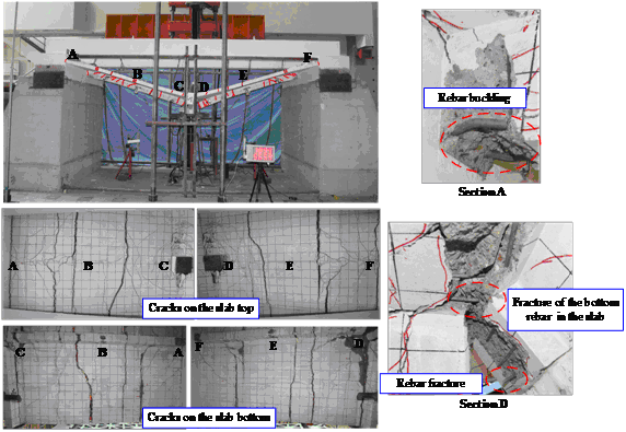
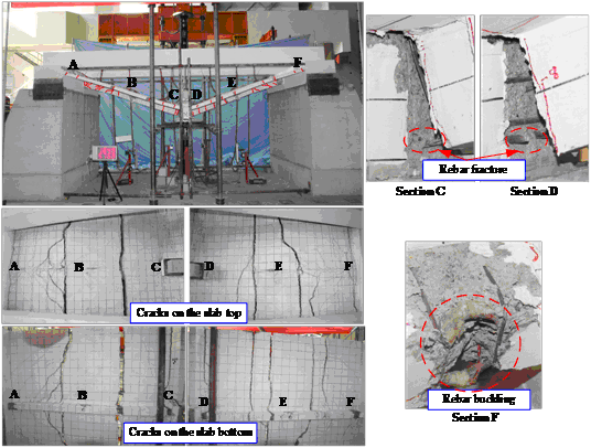
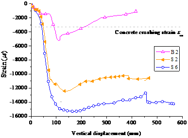
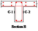
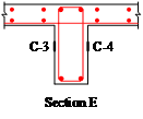
Six typical sections along the beam are defined as Sections A through F, as shown in Figure 5. To measure the displacements at the critical locations, LVDTs were installed at the four corners of the concrete stub and at the mid-span of each beam (i.e., Sections B and E) (Figure 2a). To monitor the strains within the specimens, strain gauges were placed to the steel bars in the beams and slabs at Sections A through F. In addition, strain gauges in concrete were installed at the mid-heights of Sections B and E, shown as C-1 through C-4 in Figure 5.

Figure 5 Details of test setup and arrangement of instrumentation (units: mm)

Figure 5 Details of test setup and arrangement of instrumentation (units: mm)

Figure 5 Details of test setup and arrangement of instrumentation (units: mm)

(c) Locations of the concrete strain gauges

(a) Elevation view

Figure 5 Details of test setup and arrangement of instrumentation (units: mm)

(b) Plan view

Note: Labels A through F mean the critical sections of the beam.

Figure 5 Details of test setup and arrangement of instrumentation (units: mm)

3 Experimental results

3.1 Beam specimens

The deformation of the specimens is represented by the vertical displacement of the removed column. The load-displacement curves of the beam specimens (B2 and B3) are shown in Figure 6. The mechanical response of the specimens can be classified into two stages. In the first stage, which was under the small deformation, the load was resisted by the flexural capacity of the beam, and CAA was developed in the specimens. This load-deflection characteristic was typically referred to as the beam mechanism [8]. In the second stage, which occurred under the large deformation, the load was resisted by the tensile force in the reinforcement, namely, the catenary mechanism. Taking the load-displacement curve of B2 as an example, three key points are identified on the curve: (1) the first peak point under the beam mechanism (Db, Fb), (2) the second peak point under the catenary mechanism (Dc, Fc), and (3) the transition point between these two mechanisms (Dt, Ft). Note that D and F denote the displacement and the force, respectively. The corresponding forces at these three points are listed in Table 3 for all the specimens.

Table 3 Progressive collapse resistances of the tested specimens


B2

B3

S2

S3

S4

S5

S6

Fb / kN

34

41

48

75

47

57

47

Ft / kN

17

21

35

57

42

47

44

Fc / kN

58

42

93

181

164

187

142

Fc / Fb

1.71

1.02

1.94

2.41

3.49

3.28

3.02

Figure 6 Load-displacement curves of B2 and B3

Figure 6 Load-displacement curves of B2 and B3

For B2, at a displacement of 6 mm, flexural cracks were observed at the bottom of Sections C and D and at the top of Sections A and F. When the displacement reached 45 mm, concrete crushing was observed at the top of Section D. As Figure 6 shows, the displacement is greater than Db which is corresponding to the first peak load Fb. The flexural capacity of the beam ends then decreased steadily, resulting in a decrease in the vertical resistance. When the displacement reached 150 mm, the concrete had been completely crushed and spalled on the compression side of Sections A, F, C, and D. At the same time, wide cracks were observed in Sections C and D, and the vertical resistance began to increase again. This is because the beam mechanism was replaced by the catenary mechanism in resisting the load. As the displacement increased further, the tensile cracks gradually propagated and were distributed along the full length of the beam. At a displacement of 421 mm, two bottom rebars in Section C ruptured simultaneously, which resulted in a sudden drop in the load-displacement curve. The loading process continued until the displacement reached 447 mm and subsequently terminated because of the significantly decreased load. The final failure mode of B2 is shown in Figure 7.

Figure 7 Failure mode of Specimen B2

Figure 7 Failure mode of Specimen B2

The final damage mode for B3 was similar to that of B2. The difference was that, for B3, the top rebars in Sections A and F ruptured rather than the bottom rebars in Sections C and D, and the rotations of Sections A and F were much larger than those of Sections C and D (Figure 8). As Figure 6 shows, under the beam mechanism, FbB3 was 21% larger than FbB2, because of the increase in the beam height (hbB3 was 18% greater than hbB2). In addition, DtB3 was greater than DtB2, which indicated that the transition from the beam mechanism to the catenary mechanism was delayed in B3. The reason for this is that, because of the greater beam height, the depth of the compressive zone of B3 was larger, which resulted in a greater axial compressive CAA force and in turn delayed the transition from one mechanism to the other. This phenomenon can also be illustrated by the strains of gauge C-1 at Section B of B2 and B3, as shown in Figure 9. Because the bending moment at this section was very small, the section was approximately under uniaxial compression or tension. Thus, the concrete strain at 1/2 height can approximately represent the amplitude of the axial force at Section B. The compressive strain of B3 under the beam mechanism was larger than that of B2, indicating a larger axial force in B3 (Figure 9). In addition, the displacement at which the strain of gauge C-1 of B3 changed from compressive to tensile (i.e., DB3 in Figure 9) was greater than the corresponding displacement of B2 (i.e., DB2 in Figure 9), indicating that the mechanism transition of B3 was later than that of B2, i.e., DtB3 > DtB2 (Figure 6). Note that the measured concrete tension strains jumped to an unreasonable large value or dropped to a value around zero because of the failure of concrete gauges induced by concrete cracking.

Figure 8 Failure mode of Specimen B3

Figure 8 Failure mode of Specimen B3

Figure 9 Strain developments of concrete at the mid-heights of Section B of B2 and B3

Figure 9 Strain developments of concrete at the mid-heights of Section B of B2 and B3

3.2 Beam-slab substructure specimens

In S6, flexural cracks appeared at the bottom of Sections C and D when the displacement was 10 mm. When the displacement reached 16 mm, the cracks propagated to the bottom of the slab in Sections C and D. At a displacement of 40 mm, crushing of the concrete was observed in the compressive areas of Sections A and F, and the load approached the peak load Fb, as shown in the load-displacement curve (Figure 10). Buckling of the bottom rebars and spalling of the concrete in Sections F and A were observed at displacements of 65 mm and 80 mm, respectively (Figure 10). At this point, the minimum load Ft was reached, and the resistance began to increase again. When the displacement reached 140 mm, many cross-sectional cracks in the y-direction were obvious at the slab soffit. As the deformation increases, many new cracks developed in the slab, and they gradually increased in width. The widest cross-sectional cracks were observed in the sections at a distance of 500-600 mm from Sections A, F, C, and D, where the top rebars in the slab were cut off (Figure 11). The two bottom rebars in Section D ruptured at displacements of 455 mm and 462 mm, resulting in two significant drops in the load-displacement curve. When the displacement reached 565 mm, one of the bottom rebars of the slab in Section D ruptured, and the loading process was terminated.

Figure 10 Load-displacement curves of S6 and S4

Figure 10 Load-displacement curves of S6 and S4

Figure 11 Failure mode of Specimen S6

Figure 11 Failure mode of Specimen S6


The failure modes of S2-S5 were similar to that of S6. The failure mode and the load-displacement curve of S4 are shown in Figures 12 and 10 as examples. As Figures 11 and 12 show, the failure mode of the beam-slab substructure specimens differed in three significant aspects from that of the beam specimens B2 and B3 (see Figures 7 and 8):

Figure 12 Failure mode of Specimen S4

Figure 12 Failure mode of Specimen S4

(1) For the beams of Specimens S4 and S6, the concrete compressive zones in Sections A and F were severely damaged, with large areas of concrete spalling and rebar buckling. The reason for this is that the slab was equivalent to a flange of the beam, and thus the slab reinforcement increased the tensile reinforcement ratio of Sections A and F, which resulted in an over-reinforced failure mode. Based on the deformation compatibility equation, the critical tensile reinforcement area for over-reinforced damage in Sections A and F can be calculated. The calculated values for S4 and S6 are both 623mm2; while the actual values were 801 mm2 and 694 mm2, respectively. Hence, the over-reinforced damage occurred in Sections A and F of S4 and S6. This can also be confirmed by the measured strains of the rebars in Section A of S4 and S6 given in Figure 13. When S4 and S6 reached the first peak point Fb, the tensile strains of the top rebars were smaller than the yield strain of steel, ey, whilst the compressive strains of the bottom rebars were larger than the crashing strain of concrete, ecu. This was a typical over-reinforced failure.

Figure 13 Strains developments of the rebars at Section A of S4 and S6

Figure 13 Strains developments of the rebars at Section A of S4 and S6

(2) Under the beam mechanism, the compressive zones in Sections C and D in S4 and S6 were much shorter and wider leading to increased areas and decreased compressive stresses. Consequently, the compressive failure of the concrete was less severe than that in the beam specimens. This can also be confirmed by the strains of the beam rebars at Section C of all specimens under Fb as shown in Figure 14. The heights of the compressive zones of the beam-slab specimens were much smaller than those of the beam specimens.

Figure 14 Strains of the beam rebars at Section C of all specimens under Fb

Figure 14 Strains of the beam rebars at Section C of all specimens under Fb

(3) For the beam specimens, the cracks along the beam length were mainly perpendicular to the beam axis. However, for the beam-slab substructure specimens (S4 and S6), the cracks near Sections A and F were mainly inclined. The reason for this is that the slab significantly improved the flexural capacity of the beam, while the improvement in the shear capacity was limited. Therefore, for the beam-slab substructure specimens, the development of the inclined cracks near Sections A and F was more pronounced.

The typical damage phenomena and the corresponding displacements of the specimens are listed in Table 4. The damage process can be summarized as follows: (1) formation of concrete tensile cracks at the bottom of Sections C and D and at the top of Sections A and F, (2) concrete crushing at the bottom of Sections A and F, (3) cross-sectional cracking in the specimens when the beam mechanism transits to the catenary mechanism, and (4) rupture of the bottom rebar in Sections C\D, leading to significant drops in the vertical resistance (except for B3, in which one of the top rebars at Section A ruptures).

Table 4 Experimental phenomena and corresponding joint displacements (units: mm)

Typical phenomenon

Joint displacement (mm)

B2

B3

S2

S3

S4

S5

S6

Flexural cracks at the bottom of Sections C and D

6

8

6

4

8

6

10

Concrete crushing at the bottom of Sections A and F

45

32

42

40

38

30

40

Initial rupture of the bottom rebar in Section C/D

421

N/A

387

250

410

359

455

Second rupture of the bottom rebar in Section C/D

421

N/A

387

305

474

424

462

Rupture of the top rebar in Section A/F

N/A

371

N/A

N/A

N/A

N/A

N/A

Rupture of the bottom rebar in the slab

N/A

N/A

N/A

N/A

565

Note: “—” indicates that there is no rebar in the slab.

As regulated in DoD 2010 [4], only when a framed beam has sufficient deformation capacity (i.e., when the rotation can reach 0.2 rad) can the tensile contribution of the reinforcement be considered in the tie force method. For the specimens tested in this study, when the rotation reached 0.2 rad, the corresponding vertical displacement was 400 mm. As Figure 15 shows, all of the initial ruptures of the beam rebars in B2, B3, S2, S4, S5, and S6 occurred close to 0.2 rad (0.21 rad, 0.19 rad, 0.19 rad, 0.21 rad, 0.18 rad, and 0.23 rad, respectively). This indicates that the beam and slab elements in these specimens can synergistically perform the catenary action to resist progressive collapse. On the other hand, because of the greater beam height, at the same vertical displacement, the strains in the bottom rebars in Sections C and D of S3 were larger than those in the other specimens, and thus, rebar rupture occurred quite earlier, at 0.13 rad. Hence, only the slab reinforcement in S3 contributed its axial capacity to perform the catenary action under a large deformation.

Figure 15 Load-displacement curves of all specimens

Figure 15 Load-displacement curves of all specimens

3.3 Effect of the slab on structural resistance

To illustrate the effect of the slabs on the progressive collapse-resisting performance of the beam-slab substructures, the load-displacement curves of S6, S2, and B2 are compared in Figure 16. The slab widths ws of S6 and S2 were 2000 mm and 685 mm, respectively, while B2 had no slab. Figure 16 shows that, considering the contribution of the slab, both S6 and S2 exhibited an increase in the progressive collapse resistance compared to that of B2: Fb increased by 38% and 41% for S6 and S2, respectively, while Fc increased by 145% and 60%, respectively (Table 3).

Figure 16 Load-displacement curves of S6, S2, and B2

Figure 16 Load-displacement curves of S6, S2, and B2

Fb under the beam mechanism is mainly affected by the flexural capacities of the negative-moment regions (Sections A and F) and the positive-moment regions (Sections C and D). In comparison to B2, the flexural capacities of the specimens with slabs (i.e., S2 and S6) were obviously greater because of the flexural contribution of the slabs. However, the flexural capacities of FbS2 and FbS6 were similar to each other because the slab of S6 outside the effective flange width contributed little to the flexural resistance.

In contrast, the resistance of the catenary mechanism is provided by all of the reinforcement in the slabs and beams. Because S2 had more reinforcement in the slab than B2 and because S6 had a wider slab and more slab reinforcement than S2, the resistance Fc under the catenary mechanism satisfied FcB2 < FcS2 < FcS6 (58 kN, 93 kN, and 142 kN, respectively).

The deformation corresponding to the transition point between the two mechanisms, Dt, satisfied DtS6 < DtS2 <DtB2. The reason for this is that the slab reinforcement led to an over-reinforced damage in Sections A and F. In general, the greater the slab width was, the more severe was the over-reinforced damage, because of the increase in the tensile reinforcement in the slab. This over-reinforced damage preceded the failure of the beam mechanism and brought forward the corresponding catenary mechanism, i.e., Dt was reduced. This mechanism is also demonstrated by the strain development in the bottom rebar in Section A, as is shown in Figure 17. The measured displacements at the point at which the bottom rebar in Section A yielded in compression were 31 mm, 39 mm, and 79 mm for S6, S2, and B2, respectively, indicating that the order of the end of the beam mechanism was S6, S2, and B2.

Figure 17 Strain developments of the bottom rebars at Section A of S6, S2 and B2

Figure 17 Strain developments of the bottom rebars at Section A of S6, S2 and B2

These results indicate that the existence of the slab not only improved the structural resistance under the beam mechanism and the catenary mechanism but also enhanced the transition between these two mechanisms at a smaller deformation, with less reduction in the resistance. These two advantages eventually resulted in a significantly higher progressive collapse resistance at a given deformation, when the contribution of the slab was considered. In addition, as Figure 15 and Table 3 show, except for B3, the peak load under the catenary mechanism was much larger than that under the beam mechanism, i.e., Fc was much larger than Fb. If we define Fc/Fb as a resistance increase factor, then Table 3 shows that the resistance increase factors of the beam-slab substructure specimens were significantly greater than those of the beam specimens. This indicates that a slab provided a greater enhancement to the progressive collapse resistance under the catenary mechanism than that under the beam mechanism.

3.4 Effects of various structural parameters on progressive collapse resistance

To examine the effects of various structural parameters on progressive collapse resistance, S3, S4, and S5 were designed with only one parameter was varied (i.e., the beam height, the seismic reinforcement, and the slab thickness, respectively, for the three specimens) compared to the control specimens (S6 and B2).

3.4.1 Effect of the beam height

The beam height hbS3 was 30 mm (18%) greater than hbS6, while the reinforcement in the beam and the slab remained unchanged. Under the beam mechanism, increasing the beam height resulted in an increase in the effective depth of a section. In consequence, the flexural capacity was increased, which resulted in FbS3 60% greater than FbS6 (Figure 18). Under the catenary mechanism, the two curves were very close to each other. The reason for this is that the tensile force under the catenary mechanism was provided by the reinforcement of the whole section, and S6 and S3 had an identical reinforcement area.

Figure 18 Load-displacement curves of S6, S3, and S5

Figure 18 Load-displacement curves of S6, S3, and S5

3.4.2 Effect of the slab thickness

The slab thickness tsS5 was 25 mm (50%) greater than tsS6. To satisfy the requirement of the minimum reinforcement ratio of the slab as specified in the design code [30], S5 was designed to have a larger amount of reinforcement in the slab. Hence, increasing the slab thickness resulted in a simultaneous increase in the amount of slab reinforcement. Note that this arrangement strictly complied with the actual engineering practices. A comparison of the load-displacement curves for S6 and S5 (Figure 18) shows that FbS5 was 21% greater than FbS6. This enhancement of Fb was attributable to the greater bending strengths at Sections A and F of S5 due to larger amount of tensile reinforcement in the slabs. In contrast, as the compressive zones in Sections C and D of S5 and S6 were much thinner than the slab thicknesses as shown in Figure 14, the increased slab concrete was in tensile and did not contribute to the flexural capacities of the sections. In addition, the larger amount of slab reinforcement in S5 also led to a more significant increase in the resistance under the catenary mechanism, as shown in Figure 18: FcS5 was 32% greater than FcS6.

3.4.3 Effect of the seismic design intensity

The seismic design intensity of S4 was much larger than that of S6: the PGA of the design earthquake was increased from 0.05 g (S6) to 0.20 g (S4) [30]. The increase in the seismic design intensity resulted in an increase in the amount of seismic reinforcement in the beam, with no increase in the slab reinforcement. The reinforcement ratio of the S4 beam was 84% greater than that of the S6 beam, whereas the reinforcement ratio of the whole S4 section was only 15% greater than that of S6. Figure 10 shows that FbS4 was not significantly greater than FbS6. Because of the over-reinforced failure in Sections A and F, increasing the reinforcement ratio had little effect on enhancing the flexural capacity, and in turn, FbS4 was not significantly greater than FbS6.

In addition, there was no significant difference in the resistance of these two specimens under the catenary mechanism: FcS4 was only 15% greater than FcS6. The reason for this is that the resistance under this mechanism relied mainly on the area of the continuous reinforcement of the whole section, which was not largely different for S4 and S6, as mentioned previously. This finding stands in stark contrast to test results obtained in other studies on beam-column substructures [33]. For such a substructure, only the frame beam provided collapse resistance, and thus, the seismic reinforcement in the beam contributed relatively more to the resistance. Under this situation, a seismic design will significantly improve the progressive collapse resistance. For example, in the study by Lew et al. [33], the peak resistance under the catenary mechanism of the special moment frame (SMF) specimen (with more stringent seismic design and detailing) was 2.25 times greater than that of the intermediate moment frame (IMF) specimen.

4. Conclusions

Five one-way beam-slab substructure specimens and two beam specimens were tested subjected to the removal of the middle column to investigate their progressive collapse-resisting performance. The following conclusions are drawn from the test results:

(1) The load-displacement curves of both the beam-slab substructure specimens and the beam specimens can be summarized as a two-mechanism process: at small deformations, the load was resisted by the beam mechanism; whereas at large deformations, the load was resisted by the catenary mechanism. The peak load under the catenary mechanism was generally higher than that under the beam mechanism; and the maximum Fc/Fb reached 3.49 in the tests. The resistance increase factors of the beam-slab substructure specimens were much larger than those of the beam specimens.

(2) An RC slab can substantially increase the structural resistance of the specimen not only under the beam mechanism but also under the catenary mechanism. The influence of a slab on the failure mechanism of a beam-slab substructure was that, under the beam mechanism, the existence of the slab led to an over-reinforced damage in the compressive zones of the beam ends, which accelerated the failure of the beam mechanism and the presence of the catenary mechanism.

(3) The progressive collapse resistance under the beam mechanism was mainly influenced by the beam height, slab width and seismic reinforcement in the beams. The influence of the slab width became insignificant when exceeding the effective flange width. Increasing slab thickness simultaneously increased the amount of slab reinforcement according to the minimum requirement of reinforcement ratio for the slabs and in turn enhanced the progressive collapse resistance. The resistance under the catenary mechanism relied mainly on the area of the continuous reinforcement of the whole section. The seismic design requirement resulted in an increase of the longitudinal reinforcement for the beam but not for the slab. Thus, the total reinforcement amount for the entire composite beam-slab section was not significantly increased, and in turn, the collapse resistance of the beam-slab substructures tested in this study was slightly enhanced.

Acknowledgment

The authors are grateful for the financial support received from the National Basic Research Program of China (973 Program) (No. 2012CB719703), the National Natural Science Foundation of China (No. 51578018, No. 51208011) and the Australian Research Council through an ARC Discovery Project (DP150100606).

References

[1]      American Society of Civil Engineers (ASCE). Minimum design loads for buildings and other structures (ASCE7-10). Reston (VA); 2010.

[2]      European Committee for Standardization. EN 1991-1-7: Eurocode 1: Actions on structures. Part 1-7: general actions - accidental actions. Brussels (Belgium); 2006.

[3]      British Standard Institute. BS8110: Structural use of concrete, part 1: code of practice for design and construction. United Kingdom; 1997.

[4]      Department of Defense (DoD). Unified facilities criteria (UFC): design of structures to resist progressive collapse. Washington (DC); 2010.

[5]      General Service Administration (GSA). Alternate path analysis & design guidelines for progressive collapse resistance. Washington (DC); 2013.

[6]      Izzuddin BA, Vlassis AG, Elghazouli AY, Nethercot DA. Progressive collapse of multi-storey buildings due to sudden column loss-part I: simplified assessment framework. Eng Struct 2008;30(5):1308-18.

[7]      Xu G, Ellingwood BR. An energy-based partial pushdown analysis procedure for assessment of disproportionate collapse potential. J Constr Steel Res 2011;67(3):547-55.

[8]      Li Y, Lu XZ, Guan H, Ye LP. An improved tie force method for progressive collapse resistance design of reinforced concrete frame structures. Eng Struct 2011;33(10):2931-42.

[9]      Li Y, Lu XZ, Guan H, Ye LP. An energy-based assessment on dynamic amplification factor for linear static analysis in progressive collapse design of ductile RC frame structures. Adv Struct Eng 2014;17(8):1217-25.

[10]  Li Y, Lu XZ, Guan H, Ye LP. Progressive collapse resistance demand of RC frames under catenary mechanism. ACI Struct J 2014;111(5):1225-34.

[11]  Tsai MH, Lin BH. Investigation of progressive collapse resistance and inelastic response for an earthquake-resistant RC building subjected to column failure. Eng Struct 2008;30(12):3619-28.

[12]  Brunesi E, Nascimbene R, Parisi F, Augenti N. Progressive collapse fragility of reinforced concrete framed structures through incremental dynamic analysis. Eng Struct 2015;104:65-79.

[13]  Fascetti A, Kunnath SK, Nistico N. Robustness evaluation of RC frame buildings to progressive collapse. Eng Struct 2015;86:242-9.

[14]  Li M, Sasani M. Integrity and progressive collapse resistance of RC structures with ordinary and special moment frames. Eng Struct 2015;95:71-79.

[15]  Kazemi-Moghaddam A, Sasani M. Progressive collapse evaluation of Murrah Federal Building following sudden loss of column G20. Eng Struct 2015;89:162-71.

[16]  Qian K, Li B, Ma JX. Load-carrying mechanism to resist progressive collapse of RC buildings. J Struct Eng-ASCE 2015;141(2):04014107. DOI: 10.1061/(ASCE)ST.1943-541X.0001046

[17]  Yi WJ, He QF, Xiao Y, Kunnath SK. Experimental study on progressive collapse-resistant behavior of reinforced concrete frame structures. ACI Struct J 2008,105(4):433-9.

[18]  Su YP, Tian Y, Song XS. Progressive collapse resistance of axially-restrained frame beams. ACI Struct J 2009;106(5):600-7.

[19]  Yap SL, Li B. Experimental investigation of reinforced concrete exterior beam-column subassemblages for progressive collapse. ACI Struct J 2011;108(5):542-52.

[20]  Yu J, Tan KH. Structural behavior of RC beam-column subassemblages under a middle column removal scenario. J Struct Eng-ASCE 2013;139(2):233-50.

[21]  Kang SB, Tan KH, Yang EH. Progressive collapse resistance of precast beam-column sub-assemblages with engineered cementitious composites. Eng Struct 2015;98:186-200.

[22]  Qian K, Li B. Slab effects on the response of reinforced concrete substructures after loss of corner column. ACI Struct J 2012;109(6):845-55.

[23]  Qian K, Li B. Quantification of slab influences on the dynamic performance of RC frames against progressive collapse. J Perform Constr Fac-ASCE 2015;29(1):04014029. DOI: 10.1061/(ASCE)CF.1943-5509.0000488

[24]  Pham XD, Tan KH. Experimental study of beam-slab substructures subjected to a penultimate-internal column loss. Eng Struct 2013;55:2-15.

[25]  Gouverneur D, Caspeele R, Taerwe L. Experimental investigation of the load-displacement behaviour under catenary action in a restrained reinforced concrete slab strip. Eng Struct 2013;49:1007-16.

[26]  Park R, Gamble W. Reinforced concrete slabs. New York: John Wiley & Sons; 2000. p. 716.

[27]  Bailey CG. Membrane action of unrestrained lightly reinforced concrete slabs at large displacement. Eng Struct 2001;23(5):470-83.

[28]  Foster SJ, Bailey CG, Burgess IW, Plank RJ. Experimental behaviour of concrete floor slabs at large displacements. Eng Struct 2004;26(9):1231-47.

[29]  Pham XD, Tan KH. Membrane actions of RC slabs in mitigating progressive collapse of building structures. Eng Struct 2013;55:107-15.

[30]  Ministry of Housing and Urban-Rural Development of the People’s Republic of China (MOHURD). Code for design of concrete structures. (GB50010-2010). Beijing; 2010.

[31]  Ministry of Housing and Urban-Rural Development of the People’s Republic of China (MOHURD). Code for seismic design of buildings. (GB50011-2010). Beijing; 2010.

[32]  Abrams DP. Scale relations for reinforced concrete beam-column joints. ACI Struct J 1987;84:502-12.

[33]  Lew HS, Bao Y, Sadek F, Main JA, Pujol S, Sozen MA. An experimental and computational study of reinforced concrete assemblies under a column removal scenario. NIST Technical Note 1704. Gaithersburg, MD: National Institute of Standards and Technology; 2011.


tables and figures

List of Tables

Table 1.                     Sectional sizes of the prototype structure and the control specimen

Table 2.                     Cross-sectional dimensions and reinforcement details (units: mm)

Table 3.                     Progressive collapse resistances of the tested specimens

Table 4.                     Experimental phenomena and corresponding joint displacements (units: mm)

List of Figures

Figure 1.                   The prototype structure (units: m)

Figure 2.                   Dimensions of the control specimen (units: mm)

Figure 3.                   Details of the reinforcement in S6 (units: mm)

Figure 4.                   Test setup

Figure 5.                   Details of test setup and arrangement of instrumentation (units: mm)

Figure 6.                   Load-displacement curves of B2 and B3

Figure 7.                   Failure mode of Specimen B2

Figure 8.                   Failure mode of Specimen B3

Figure 9.                   Strain developments of concrete at the mid-heights of Section B of B2 and B3

Figure 10.               Load-displacement curves of S6 and S4

Figure 11.               Failure mode of Specimen S6

Figure 12.               Failure mode of Specimen S4

Figure 13.               Strains developments of the rebars at Section A of S4 and S6

Figure 14.               Strains of the beam rebars at Section C of all specimens under Fb

Figure 15.               Load-displacement curves of all specimens

Figure 16.               Load-displacement curves of S6, S2, and B2

Figure 17.               Strain developments of the bottom rebars at Section A of S6, S2 and B2

Figure 18.               Load-displacement curves of S6, S3, and S5


* Corresponding author, Email: luxz@tsinghua.edu.cn

Introduction
Research
Application
Teaching
Publications
Download
Issues
Others


Our Lab

Collapse Prevention Committee