Numerical Simulation for the Progressive Collapse of Concrete Building due to Earthquake

Xinzheng Lu1,2, Xuchuan Lin1, Yuhu Ma1, Yi Li1, Lieping Ye1,2

1Department of Civil Engineeringy, Tsinghua University, Beijing,China

2 Key Laboratory of Structural Engineering and Vibration, Ministry of Education, Beijing, China Beijing,China

Email: luxz@tsinghua.edu.cn

Proc. the 14th World Conference on Earthquake Engineering,
October 12-17, 2008, Beijing, China, CDROM.

Download PDF version

Recommended reading: "Collapse simulation of reinforced concrete high-rise building induced by extreme earthquakes, Earthquake Engineering & Structural Dynamics, 2013, 42(5): 705-723".

ABSTRACT :

Collapse is a critical ultimate state for buildings under earthquake. Though collapse should theoretically be avoid for any buildings under any earthquake, it is still very important to study the collapse behavior of buildings so as to get a better understanding for the collapse mechanism and to find efficient method to against it. Progressive collapse, which means that collapse of whole building due to local weak stories or weak zones, is a most common failure mode in earthquake. And as its collapse process highly depends on the whole structural system, numerical simulation becomes a major method to study it. With the fiber-beam-element model and multi-layer-shell-element model, which is developed by Tsinghua University for reinforced concrete (RC) frames and RC shear-walls respectively, the extreme nonlinear behavior of RC structural elements can be properly simulated including the cycle behavior under coupled axial force-bending moment-shear force, the breakdown of structural elements at ultimate states, and the contact between structural elements during the collapse. Simple RC frames and RC frame-shear wall structures are firstly used to demonstrate and to benchmark the capacity of the numerical model, and real complicated buildings are analyzed to study the failure mechanism of the structures.

KEYWORDS:

progressive collapse, earthquake, numerical model, nonlinear, reinforced concrete

1.Introduction

Collapse is a critical ultimate state for structures under severe earthquakes. A typical collapse mode is that yielding firstly appears at the weak part of the structure and then results in large concentrated deformation and local failure. Unless a structure has a good alternative loading path, local failure will expand to other parts and finally cause a global collapse, which is referred as progressive collapse. To improving the seismic performance of structure, it is significant to understand the progressive collapse behaviors of structures under earthquakes. Because in such failure mode, the global strength of structure is determined by the failure of the weakest element, and the strengths of other elements can not be fully used. On the contrary, if the weakest part is found and properly strengthened, the global anti-collapse capacity of structure will be effectively enhanced.

Collapse of structures is a failure mode which is difficult to be simulated with physical tests. So numerical simulation is an important approach to study it and a great mount of researches (Lynn & Isobe 2007; Mattern et al 2007;Lynn & Isobe 2006; Pekau & Cui 2006; Khandelwal & El-Tawil 2005; Kaewkulchai & Williamson 2004; Isobe & Tsuda 2003; Xuan et al 2003; Lu & Jiang 2001; Toi & Isobe 1999) has been conducted in this field. Generally, structural collapse is a complicated numerical process that a continuous body changes to a discrete one. The elasto-plastic deformation and the energy dissipation before collapse should be accurately simulated in the numerical model, as well as the rigid body movement and impact/contact of structural fragments during collapse process, which brings very high requirement to the numerical model. Though some researchers (Zhou et al 2005; Munjiza 2004; Jia & Yu 2001; Qin & Fan 2001) have simulated some collapse cases based on discrete element models (DEM), these works still have a long way to go to the engineering practice because of the difficulty in simulating the complicated structural behavior before collapse with DEM. With the introduction of elemental nonlinearity (activate or deactivate elements) and nonlinear contact, the model, based on finite element method (FEM), can give a precise simulation of structural behaviors before collapse and an acceptable simulation at early stage of collapse. And the FE models have many mature software or codes to simplify the engineering practice (Jiang et al 2005). Especially for the progressive collapse under earthquakes, the key issues concerned in the simulation are the location of the weakest part and the chains reaction from local damage, so FEM have more advantages in this problem. Thus, based on the FE method, the fiber-beam-element model for beam-column structures and the multi-layer-shell -element for shear wall structures are proposed in the paper. By choosing proper criterion to deactivate elements and adopting appropriate contact algorithm, the models proposed are able to simulate the whole process of structural collapse under earthquakes.

2.Numerical model

2.1.Fiber-beam-element model

Beam-column structural elements such as frames or bridge piers can be simulated with fiber-beam-element model together with one dimensional material constitutive law (Jiang et al 2006). In the fiber beam element model, the beam section is divided into a number of fibers, whose material property is described with uniaxial stress-strain model, and the deformation among fibers follows plane section assumption. A fiber model program referred as THUFIBER was developed by the authors and it is embedded into the general finite element program MSC.MARC. The beam section of the model is shown in figure 1 and the number of concrete fibers or reinforcement fibers can be changed according to the need of calculation. For concrete material, L¨¦ & Paultre model (L¨¦geron & Paultre 2003) was modified to take account of more complicated behaviors, such as confining, cracking , degrading and hysteretic loading, and the typical uniaxial stress-strain relation of concrete in THUFIBER is shown in figure 2. For steel material, a new model (Wang et al 2007) based on L¨¦geron model is developed to simulate the behaviors of yielding, hardening, softening and Bauschinger¡¯s effect, shown as figure 3, and the model match well with the results from the material tests (L¨¦geron et al 2005).

Member section

Stress-strain curve of concrete

Figure 3 Stress-strain curve of steel

Figure 1 Member section

Figure 2 Stress-strain curve of concrete

Figure 3 Stress-strain curve of steel

Comparison between simulation and test result of S-1

Comparison between simulation and test result of YW0

Figure 4 Comparison between simulation and test result of S-1

Figure 5 Comparison between simulation and test result of YW0

Two compressive-flexible column tests, whose specimen are denoted as S-1 (Zatar et al 2002) and YW0 (Li 2003) respetively, were simulated to verify the proposed fiber beam element model. S-1 has a larger reinforcement ratio (2.65%) and a smaller axial compressive ratio (0.03) while YW0 has a smaller reinforcement ratio (1.29%) and a larger axial compressive ratio (0.44). The simulation agrees with the experiment (Zatar & Mutsuyoshi 2002; Li 2003) fairly well and the comparisons of load-displacement relation curves for S-1 and YW0 are shown in figure 4 and Fig5 respectively. A test on the collapse process of a four-bay three-story planar frame (Yi et al 2007) is also simulated. The comparison for the unloading curves of the middle column between test and simulation are shown in figure 6(a) and the displacement of measuring points at the top of columns on the first floor is shown in figure 6 (b). It is clear that the simulation results in figure 6 are coincident well with test results. The comparisons above indicate that fiber beam element model proposed is able to simulate mechanical behavior and collapse process of RC members under seismic loads.

Comparison of THUFIBER program results to experimental results

Comparison of THUFIBER program results to experimental results

(a) Unloading curve of middle column

(b) Displacement at the top of first-story columns

Figure 6 Comparison of THUFIBER program results to experimental results

2.2.Shear wall model based on multi-layer-shell-element

The proposed multi-layer-shell-element is based on the principles of composite material mechanics and it can simulate the coupled in-plane/out-plane bending and the coupled in-plane bending-shear nonlinear behaviors of RC shear wall. Basic principles of multi-layer-shell-element are illustrated by figure 7. The shell element is made up of many layers with different thickness and different material properties (Men et al 2006). The rebars are smeared into one layer or more. The rebar layers can be either isotropic or orthotropic depending on the reinforcement ratio in the longitude and transverse directions, as shown in figure 8. Since the multi-layer shell model relates the nonlinear behaviors of the shear wall to the constitutive laws of concrete and steel directly, it has many advantages to represent the complicated nonlinear behaviors compared with the existing equivalent-beam model, such as equivalent-truss model and the multi-component-in-parallel model (Jiang et al 2006).

Multi-layer shell element

Location of the rebar layers

Figure 7 Multi-layer shell element

Figure 8 Location of the rebar layers

A shear wall test (Wei 2006) was simulated to validate the shear wall model based on the multi-layer-shell-element. The shear wall specimen has a height of 2550mm, a width of 1100mm and a thickness of 140mm, other information can be found in the literature (Wei 2006). In the shear wall model, the Micro-Plane concrete material model (Miao et al 2008) and Wang¡¯s steel model (Wang et al 2007), developed by the authors¡¯ research group, are applied to the concrete and rebar respectively. The cracking strain contours at the peak load state are shown in figure 9 and vertical compressive strain contours at the ultimate state are shown in figure 10. The load-displacement relation curves both for test and simulation are shown in figure 11 and they match each other well.

Cracking strain at the peak load state

Vertical compression strain at the ultimate state

Comparison of load-displacement relation curves

Figure 9 Cracking strain at the peak load state

Figure 10 Vertical compression strain at the ultimate state

Figure 11 Comparison of load-displacement relation curves

2.3.Elemental nonlinearity and contact

In the process of structural collapse, the whole structure will change from continuum into discrete parts together with structural elements break and fail. The process can be simulated by elemental nonlinearity, which will deactivate failed elements when they exceed the deformation criterion. The proposed criterion to deactivate elements are as follows: the shell element is deactivated when concrete crushes (compressive strain exceeds 0.38% ) or rebar layer breaks (average tensile strain exceeds 2%), while the beam element is deactivated when the maximum tensile strain of rebar exceeds 10%. The deactivation function is supported by the user defined subroutine UACTIVE of MSC.MARC, which can deactivate any element with any user defined criterion.

Impacting and contact of fragments during collapsing have a significant influence on the collapse process. To simulate the process above, contact relation should be assigned to elements. Because MSC.MARC provides strong ability to model complex contact phenomena, the contact simulation in collapse process can be achieved.

2.4.Examples of verification

A pseudo-dynamic test of a two-bay three-story frame with a reduced scale of 1:2 was simulated to validate the accuracy and efficiency of the fiber-beam-element-model. The first story is 1800mm high and the other two is 1500mm. The length of beams is 1500mm. The specimen during the test is shown in figure 12 and further data about the test can be found in the literature (Asad 2007). Force-drift relation curves of the three stories are given in figure 13~figure 15 respectively. It can be found that the simulation results (FEA) agree well with test data. Therefore, the fiber-beam-element-model proposed is able to simulate the seismic performance of frames accurately.

Two RC tube tests (referred as TC1 and TC2 respectively) are simulated to benchmark the proposed multi-layer ¨Cshell-model of shear wall. The size of tubes is 1380mm¡Á1380mm¡Á3690mm and more data can be found in the literature (Du et al 2007). Axial compressive ratio of TC1 and TC2 calculated with concrete actually strength are 0.15 and 0.36 respectively. Inverted triangular lateral cyclic loads are applied to the middle and the top of the tubes. The model of shear walls and coupling beams are shown in figure 16 and the arrangement of steel reinforcement in the model are shown in figure 17. All material strengths in the numerical model are provided by the tests (Du et al 2007). The reinforcement uses Wang¡¯s model (Wang et al 2007) developed by the authors¡¯ research group and concrete material uses elasto-plastic-fracture model provided by MSC.MARC. Both for TC1 and TC2, shear force-top displacement curves of simulation and test are compared as shown in figure 18 and figure 19 respectively. The results from simulation are close to those from the tests.

Frame test

Figure 13 Force-drift relation of the first floor


Figure 12 Frame test

Figure 13 Force-drift relation of the first floor


Figure 14 Force-drift relation of the second floor

Figure 15 Force-drift relation of the third floor


Figure 14 Force-drift relation of the second floor

Figure 15 Force-drift relation of the third floor


Figure 16 Concrete element mesh

Figure 17 Spatial distribution of rebar elements

Figure 16 Concrete element mesh

Figure 17 Spatial distribution of rebar elements

3.Numerical simulation of progressive collapse

3.1.Ten-storey RC frame

The collapse procedure of a simple ten-storey reinforced concrete (RC) frame is simulated with the proposed fiber beam element model (Miao et al 2007). From figure 20 it is can be found that the damage of the frame starts firstly at the columns in the 8th storey, where the column sections change, and then ground storey, where the columns have largest lateral force, at the time of 3 second. The 8th storey of the structure collapsed completely at 4.4s and at the same time very large lateral displacement occurred at the ground storey. The results of this case show a clear failure modes and collapse process under earthquake disaster. This will be very useful for studying the safety of buildings and evaluating losses during earthquakes.

Figure 18 Comparison of shear force-displacement curves (actual axial compression ratio=0.15)

Figure 19 Comparison of shear force-displacement curves (actual axial compression ratio=0.36)

Figure 18 Comparison of shear force-displacement curves  (actual axial compression ratio=0.15)

Figure 19 Comparison of shear force-displacement curves (actual axial compression ratio=0.36)

Figure 20 Deformation of the initial structure at different time(PGA=2000gal)

Figure 20 Deformation of the initial structure at different time(PGA=2000gal)

Figure 20 Deformation of the initial structure at different time(PGA=2000gal)

Figure 20 Deformation of the initial structure at different time(PGA=2000gal)

(a)  t=2s

(b)  t=3s

(c)  t=4s

(d)  t=4.4s

Figure 20  Deformation of the initial structure at different time(PGA=2000gal)

Figure 21 Collapse process of the structure (PGA=4000gal)

Figure 21 Collapse process of the structure (PGA=4000gal)

Figure 21 Collapse process of the structure (PGA=4000gal)

Figure 21 Collapse process of the structure (PGA=4000gal)

(a) The first stage

(b) The second stage

(c) The third stage

(d) The forth stage

Figure 21  Collapse process of the structure (PGA=4000gal)

3.2.High-rise frame-core tube structure

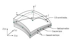
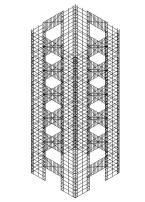
Whole collapse process of a high-rise frame-core tube building under an extremely severe earthquake is simulated. With definitions of elemental nonlinearity and contact arithmetic, the frame is modeled with the fiber-beam-element and the core tube is modeled with multi-layer-shell-element. 
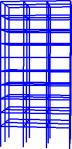
The deformation and plastic hinges in different stages are shown in figure 21. At the first stage, the building vibrates slightly around its original 
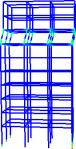
place and no damage occurs, shown as figure 21(a). At the second stage, shear walls in the weak story fail due to large compressive-shear internal force. And frame begins to yield and many plastic hinges appear around the weak story, 
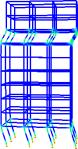
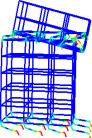
shown as figure 21(b). At the third stage and forth stage, the weak story is destroyed and the whole structure comes into a complete collapse. The structure above the failed weak story falls down and impact on the lower stories, which results in a progressive collapse. Hence, the model gives a good simulation on the failure mode and the whole collapse process of frame-core tube structure.

4.Conclusion

(1) The fiber-beam-element-model and shear wall model based on multi-layer-shell-element are proposed and validated. The simulation results agree well with the test results.

(2) Based on the models proposed, the progressive process can be simulated by setting proper criterion to deactivate elements and choosing appropriate algorithm of contact.

(3) The model and methodology proposed in this paper is of some value to study the seismic performance and collapse mechanism of buildings under severe earthquakes.

Acknowledgement

The research presented in this paper was funded by the National Key Project of Scientific and Technical Supporting Programs by Ministry of Science & Technology of China (2006BAK01A02-09).

REFERENCES

Asad U.Q.(2007). Study on Passive Control of RC Frame with High Strength Reinforcements in the Columns. PhD thesis of Tsinghua University, Beijing ,China.

Du X.L, Jia P. and Zhao J.(2007). Experimental Study On Seismic Behavior of Reinforced Concrete Core Wall under Different Axial Load Ratio. Journal of Harbin Institute of Technology 39:Sup2, 567-572.

Isobe, D., and Tsuda, M.(2003). Seismic collapse analysis of reinforced concrete framed structures using the finite element method. Earthquake Engineering and Structural Dynamics 32:13, 2027-2046.

Jia J.H. and Yu Y.L .(2001). Applying FEM and DDA to Simulate the Demolition of Frame Structure. Blasting 18:1,27-30.

Jiang J.J., He F.L., He Y.B., Lu X.Z.(2006).Finite element method and application, Chinese Machine Press,Beijing, China.

Jiang J.J., Lu X.Z., Ye L.P.(2005).Finite Elopement Analysis of Concrete Structures. Tsinghua University Press, Beijing, China.

Kaewkulchai, G. and Williamson, E.B.(2004).Beam element formulation and solution procedure for dynamic progressive collapse analysis, Computers & Structures 82:7-8,639-651.

Khandelwal, K. and El-Tawil, S. (2005). Multiscale Computational Simulation of Progressive Collapse of Steel Frames.Proceedings of the ASCE Structures Congress, May 2005.

L¨¦geron F. and Paultre, P.(2003). Uniaxial confinement model for normal and high-strength concrete columns . Structure Engineering 129:2,241¨C252.

L¨¦geron F., Paultre P. and Mazar J.(2005) Damage mechanics modeling of nonlinear seismic behavior of concrete structures. Engineering Mechanics 131:6, 946-954.

Li J.(2003). Experimental investigation and theoretical analysis on seismic behavior of FS confined concrete columns .PhD thesis of Tsinghua University, Beijing ,China.

Lu X.Z. and Jiang J.J. (2001). Dynamic finite element simulation for the collapse of world trade center. China Civil Engineering Journal 34:6,8-11.

Lynn, K.M. and Isobe, D. (2007).Structural collapse analysis of framed structures under impact loads using ASI-Gauss finite element method. International Journal of Impact Engineer 34:9, 1500-1516.

Lynn, K.M.and Isobe, D. (2006).Finite element code for impact collapse problems of framed structures. International Journal of Impact Engineer 69:12,2538-2563.

Mattern, S., Blankenhorn, G.and Breidt, M.(2007).Comparison of building collapse simulation results from finite element and rigid body models. IUTAM Symposium on Multiscale Problems in Multibody System Contacts, Springer Netherlands, 257-267.

Men J., Lu X.Z., Song E.X. and Chen Z.Y.(2006). Application of multi-layer model in shell wall computation. Protective Structure 28:3,9~13.

Miao Z. W., Lu X. Z., Ye L. P., Ma Q. L.(2007). Simulation for the Collapse of RC Frame Tall Buildings under Earthquake Disaster. Computational Mechanics, Proceedings of ISCM 2007, July 30-August 1, Beijing,China.

Miao Z.W.,Lu X.Z. ,LI Y. and Ye L.P.(2008). Analysis for Concrete Structures under Complicated Stress Conditions Based on General Purpose FE Software and Microplane Model. Journal of Shenyang Jianzhu University(Natural Science) 24:1, 49-53.

Munjiza A.(2004) .The combined finite-discrete element method for structural failure and collapse. Engineering Fracture Mechanics 71:4-6, 469-483

Pekau, O.A. and Cui, Y. (2006).Progressive collapse simulation of precast panel shear walls during earthquakes. Computers & Structures 84:5-6, 400-412.

Qin D. and Fan L.C.(2001). Numerical Simulation on Collapse Process of Reinforced Concrete Structures. Journal of Tongji University 29:1,80-83.

Toi Y. and Isobe,D.(1999) Adaptively shifted integration technique for finite element collapse analysis of framed structures. International Journal for Numerical Methods in Engineering.1999,36:14, 2323-2339.

Wang X.L., Lu X.Z. and YE L.P..(2007). Numerical Simulation for the Hysteresis Behavior of RC Columns under Cyclic Loads. Engineering Mechanics 24:12,76-81.

Wei Y.(2006). Research on seismic behavior and design method for reinforced concrete core wall-steel frame hybrid structures .PhD thesis of Tsinghua University, Beijing ,China.

Xuan G., Gu X.L. and Lu X.L..(2003). Numerical analysis of collapse process for RC frame structures subjected to strong earthquakes. Earthquake Engineering and Engineering Vibration 23:6,24-30.

Yi W.J., He Q.F. and Xiao Y.(2007). Collapse performance of RC frame structure. Journal of Building Structures 28:5,104-109,117.

Zatar W. and Mutsuyoshi H.(2002). Residual displacements of concrete bridge piers subjected to near field earthquakes . ACI Structural Journal 99:6, 740-749.

Zhou J., Qu J.T. and Jia M.C.(2005). Numerical Simulation of Concrete Frame Collapsing Process with PFC2D Program. Journal of Seismological Research 28:3,288-293.

Introduction
Research
Application
Teaching
Publications
Download
Issues
Others


Our Lab

Collapse Prevention Committee