|
Strengthening effect analysis
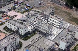
A typical RC frame classroom building
(Figure 1), which is close to the Wenchuan Earthquake epicenter, is used as
an example to analyze the strengthening effect of the steel brace. The plan
for the classroom building is shown in Figure 4. The detailed phenomenon of
seismic damage and the detailed structural information are described by Lu et
al. [16]. A steel brace is assumed to be installed in the short axis
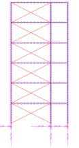
direction of the frame, along which the frame collapsed. Two schemes (i.e.,
X-shaped and A-shaped) for the steel brace installation are compared, as shown
in Figure 5. To study the influence of the cross-section and numbers of the
braces on the structural collapse resistance, five load cases are compared as
follows:
(1)
Load Case 1: The section
of the steel brace is I25A, install a suit of braces every 2 frames (Load case
No: I25).
(2)
Load Case 2: The section
of the steel brace is I20A, install a suit of braces every 2 frames (Load case
No: I20).
(3)
Load Case 3: The section
of the steel brace is I20A, install a suit of braces every 4 frames (Load case
No: I20-1/2).
(4)
Load Case 4: The section
of the steel brace is I20A, install a suit of braces every 8 frames (Load case
No: I20-1/4).
(5)
Load Case 5: The section
of the steel brace is I20A, install a suit of braces every 12 frames (Load case
No: I20-1/6).
For Load Case 5, because the number
of classrooms is limited, it is actually impossible to install a suit of braces
every 6 classroom. Hence, this case was only studied theoretically.
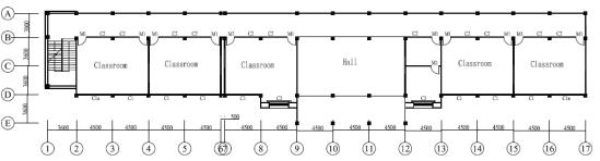
Fig. 4 Plan of the Classroom Building
The earthquake ground motions, which
are used as the input of IDA, are 22 far-field ground motions suggested by FEMA
P695 [17]. Moreover, the widely used El-Centro ground motion is also
used as the input of the IDA. The structures are modeled with the THUFIBER Program
[14], and the influences of the foundations and floor slabs are considered.
The details of the model are described by Lu et al. [16]. To allow
for the influence of the steel stirrups, the confined concrete constitutive
law that is proposed by Bousalem and Chikh [18] is used to model
the core concrete. Because of the excellent nonlinear computing ability of the
THUFIBER program, the following collapse criterion is used: the structure is
deformed so much that the structure is unable to safely provide enough free
space [14].
|
|
|
|
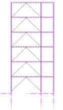
X-shaped
|
A-shaped
|
|
Fig.5 Strengthening
scheme of the Classroom Building
|
Push-over results The push-over results of different load
cases are shown in Figure 6. As the number of braces increases, the stiffness
and bearing capacity are improved. This result is the positive effect of the
brace strengthening [3]. However, the ductility of the frame decreases with an increase in
the brace number because the brace will bring additional axial force to the
column. Because the axial force ratio of the columns has approached to the ultimate
value [16], the additional axial force will result in a decrease
in the ductility of the frame. This is the negative effect of the brace strengthening
on the seismic resistance. Because both positive effect and negative effects
are observed in the push-over analysis, it is difficult to draw a conclusion
about the brace strengthening effect from the push-over results. Hence, collapsed
fragility analyses based on IDA for different load cases are analyzed as follows
to compare the effects of different strengthening schemes.
Fig.6 Push-over result of steel
brace strengthening scheme
Collapsed fragility analysis results The collapsed fragility analysis results of the steel
brace strengthening scheme are shown in Figure 7. In Figure 7, the vertical
axis is the collapsed possibility, which is the proportion of collapsed ground
motion records and total ground motion records at a given seismic intensity.
The horizontal axis is the seismic intensity, and the spectral acceleration
at structural fundamental period Sa(T1)
is used as the intensity measure. According to the work in Ref [3], [14] and
[17], Sa(T1) can reduce the dispersion of
the IDA results. It can be observed from Figure 7 that after steel brace strengthening,
the collapse possibility is reduced obviously under the maximal considered earthquake
(Sa(T1)=Sa(T1),MCE).
When Sa(T1)=2Sa(T1),MCE,
the strengthening effect is also obvious. However, when Sa(T1)
is larger than 4 times Sa(T1),MCE
(Sa(T1)>4Sa(T1),MCE),
the collapse possibility unexpectedly increases. The reasons for this increase
are as follows.
|
|
|
|
|
 |
|
 |
|
Fig.7 Collapse possibility curves of conventional
brace strengthening scheme
For RC frame structures strengthened
with braces, the braces have two effects on the seismic resistance of the structure.
On one hand, the structural bearing capacity is enhanced, and the energy dissipation
capacity is improved due to the plastic deformation of the brace. Therefore,
the structural collapses resistance is improved. On the other hand, the structural
stiffness is enhanced, so the seismic load is increased. Furthermore, the axial
forces of columns are increased due to the axial load of the brace. Therefore,
the deformation capacities of columns are reduced, which will weaken the structural
collapse resistance.
In general, if the energy input of ground
motion is relatively stable or the ground motion intensity is small, the energy
dissipation capacity of the braces will be fully used. Hence, the structural
collapse resistance will be improved. However, if the earthquake is pulse-type
or the ground motion intensity is large, the structure will collapse very quickly,
and the energy dissipation capacity of the braces will not be fully used. In
this situation, the negative effect due to the increasing axial force in the
column will be a dominant factor.
Typical failure modes of the steel brace¨Cstrengthened structures are shown in Figure 8. Figure 8a
shows the failure mode in which the collapse resistance is improved after strengthening;
the input ground motion record is from Kobe, Japan, 1995. Without strengthening,
the structure will collapse when Sa is larger than 2.5 m/s.
After strengthening, the structure will collapse when Sa is
larger than 4.9 m/s. Subjected to this ground motion, the structure has experienced
a few of cycles of vibration before it collapses, and the energy dissipation
capacity of the braces has been fully used. The structural plastic hinges are
uniformly distributed, which also provides a better energy dissipation capacity.
In Figure 8b, the input ground motion record is from Duzce, Turkey, 1999. Without
strengthening, the structure will collapse when Sa is larger
than 7.35 m/s. After strengthening, the structure will collapse when Sa
is larger than 4.9 m/s. Hence, the structural collapse resistance is reduced
because the Duzce record is a pulse-type earthquake. After the first pulse,
the top of the side column in the bottom story has been destroyed because the
deformation is too large. The energy dissipation capacity of the braces cannot
be fully utilized. Moreover, the number of plastic hinges inside the building
is also very limited. The energy dissipation capacity of the structure is not
fully developed.
|
|
|
|
(  Plastic hinges
in beams£¬ Plastic hinges
in beams£¬  Plastic hinges
in columns£¬ Plastic hinges
in columns£¬  Destroy position) Destroy position)
|
|
(a) Kobe, Japan, 1995 earthquake input
|
(b) Duzce,
Turkey, 1999 earthquake input
|
|
Fig. 8 Failure mode of a conventional
brace strengthened¨Cstructure
|
The collapse possibilities of different
steel brace strengthening schemes are shown in Table 2. In Table 2, the collapse
margin ratio (CMR) is defined as:
 (1)
(1)
where Sa(T1)50%collapse
is the intensity of the input motions under which 50% of the ground motions
will cause structural collapse. Sa(T1)MCE
is the maximal considered earthquake intensity. The larger CMR is, the better
the structural collapse resistance is. The CMR does not change monotonically
with the brace number. Therefore, there is an optimal number for the brace strengthening
scheme. Among these cases, Load Case 4 is the best choice.
Tab. 2 Collapse possibility of the conventional
brace-strengthening scheme
|
Load cases
|
X-shaped
|
A-shaped
|
|
CMR
|
Sa(T1)/Sa(T1),MCE
|
CMR
|
Sa(T1)/Sa(T1),MCE
|
|
1.0
|
2.0
|
1.0
|
2.0
|
|
I25
|
4.05
|
0.0%
|
0.0%
|
4.05
|
0.0%
|
0.0%
|
|
I20
|
3.91
|
0.0%
|
0.0%
|
4.28
|
0.0%
|
0.0%
|
|
I20-1/2
|
4.02
|
0.0%
|
0.0%
|
4.49
|
0.0%
|
0.0%
|
|
I20-1/4
|
4.91
|
0.0%
|
0.0%
|
4.49
|
0.0%
|
0.0%
|
|
I20-1/6
|
4.74
|
0.0%
|
1.5%
|
4.49
|
0.0%
|
0.0%
|
To compare the influence of different
brace arrangements, the I20 Load Case is used as an example, and the comparison
of the collapse possibilities is shown in Figure 9. With the same number and
section of braces, the strengthening effect of the A-shaped brace is better
than that of the X-shaped brace. This result is obtained because the X-shaped
braces will bring more axial force to the bottom columns, which is unfavorable
for structural collapse resistance.

      
Fig.
9 Comparison of the collapse possibility curves of steel
brace strengthening schemes
|