Experimental Study and Finite Element Analysis of Energy Dissipating Outriggers

Qingshun Yang1, Xinzheng Lu1 * , Cheng Yu2, and Donglian Gu3

Advances in Structural Engineering,2017, 20(8): 1196-1209.

DOI: 10.1177/1369433216677122.

Download PDF Version

Abstract: The outriggers are widely adopted in tall and super-tall buildings. Their energy dissipation capacity can significantly influence the nonlinear seismic responses of the entire building structure. Based on an actual tall building project, the structural responses and energy dissipation capacities of three different outriggers were studied through experiments and finite element analyses. The test results of conventional outrigger specimen showed a steep deterioration after peak strength and an unfavorable energy dissipation capacity due to the global buckling of the braces and the local buckling of the chords after flexural yielding. By using buckling restrained braces (BRBs) and reduced beam sections (RBSs) in a new design of outriggers, the energy dissipation capacity and the ductility of outriggers were significantly improved. The yield and peak strengths were further improved with the use of high strength steel in chords on a third specimen. The finite element (FE) simulation of the three specimens indicated that the initial imperfection of the specimens shall be considered, and the developed FE models yielded good agreements with the test results. The outcome of this work can provide additional references for the application of outriggers in tall buildings.

Keywords: outrigger, tall building, earthquake, buckling, buckling restrained brace, reduced beam section


If you need the PDF version of this paper, please email to luxinzheng@sina.com

Introduction

In recent years, a number of tall and super-tall buildings have been constructed world widely. How to effectively control the lateral displacement of tall buildings has become a key challenge of engineering design. The lateral displacement of tall buildings can be efficiently reduced by installing outriggers that connect the core tubes and the perimetric frames (Deng et al., 2014; Lu et al., 2015). Therefore, the outriggers were widely used in recently built tall and super-tall buildings. Meanwhile, many corresponding research projects have been performed on the seismic performance of outriggers.

Taranath (1975), Mcnabb and Muvdi (1975), Smith and Coull (1991), Hoenderkamp (2008) and Nanduri et al. (2013) analyzed the elastic responses of buildings with different numbers of outriggers at various positions. Their research outcomes indicated that the lateral stiffness of buildings would be improved effectively if the outriggers were installed in the middle or upper part of the buildings (e.g., the roof or the 2/3 height).

Further research work studied the seismic performance of outriggers at the nonlinear stage of the structures. Li and Wu (2004), Poon et al. (2011), Jiang et al.(2014) and Lu et al. (2011, 2013, 2014, 2016) found that the outriggers could dissipate a great deal of the seismic energy after yielding, which would significantly influence the nonlinear seismic responses of buildings. Moehle (2015) indicated that the outriggers could be designed to yield and fail as  ¡°fuses¡± of the building, to dissipate the seismic energy and to protect the primary structure. As a result, the nonlinear performance of outriggers is also very important in determining the seismic behavior of the entire building structure. Chen et al. (2013) and Nie and Ding (2013) experimentally studied the nonlinear behavior of the outriggers. Their experiments found that global or local buckling occurred in the conventional outriggers, which significantly limited the energy dissipation capacity. Therefore, how to improve the energy dissipation capacity of the outriggers has attracted the focus of many researchers.

In order to improve the energy dissipation capacity of conventional outriggers, some researchers added viscous dampers to the outriggers. Smith and Willford (2007) proposed to add viscous dampers between the outriggers and the perimetric frames to reduce the structural response. Chang et al. (2013) and Asai et al. (2013) proposed and tested a smart damped outrigger system using magnetorheological dampers. Zhou and Li (2014) suggested that the viscous dampers were installed to the outriggers not only in the boundary areas connecting to the perimetric frames, but also within the outriggers.

Although viscous dampers have satisfactory seismic performance, the design and analysis procedure of viscous dampers are relatively complicated. In contrast, the buckling-restrained brace (BRB) is much more familiar to structural engineers and much easier to design (Black et al., 2004). Therefore, some researchers proposed to use BRBs to improve the energy dissipation capacity of outriggers (O¡¯Neill, 2006; Youssef et al., 2010; Zhou et al., 2012, 2014). However, most of previous research efforts were theoretically works and experimental validations were lacking.

The research presented here used an actual tall building project as the reference and studied a typical outrigger system in this building with the braces replaced by BRBs. The seismic performances of three different outriggers were analyzed through experiments and finite element (FE) simulations. The outcome of this work can provide additional references for the application of outriggers in tall buildings.

Overview of the background project and the specimen design

The referred tall building project is shown in Figure 1(a) with a total height (H) of 249.6 m. It is located in an 8-degree seismic design region of China (MOHURD, 2010) [i.e., the corresponding PGA (peak ground acceleration) value of the design earthquake (i.e., exceedance probability of 10% in 50 years) is 200 cm/s2]. The widely used frame-core tube-outrigger system is adopted for this building. There are three sets of steel outriggers in the tall building, which are located at the height of 0.3 H, 0.54 H and 0.83 H, respectively.

The background building project and the sketches of three different specimens

Figure 1. The background building project and the sketches of three different specimens.

Note ¡° ¡± indicate RBS

A typical outrigger located at 0.54 H of the building is selected as the prototype outrigger, as shown in Figure 1(a). The prototype outrigger is a ¡°V¡±-shaped truss with a length of 9.2 m and a height of 5.5 m, as shown in Figure 1(b). Numerous researchers (Kumar et al., 1997; Kim et al., 2004) have proven that a scaled model can simulate the behavior of the prototype model well if a suitable scale ratio is adopted. Meanwhile, the scale ratio should meet the requirements of the code such as Chinese Specification for Seismic Test of Buildings (JGJ/T 101-2015) (MOHURD, 2015). Based on these literatures and due to the limitation of the space and the loading capacity of the laboratory, a 1/3-scaled model was adopted in this research. Many test results (e.g. Hitaka and Matsui, 2003; Dan et al., 2011) have demonstrated the 1/3-scale model can appropriately represent the properties of prototype structures.

This study designed and tested three different specimens, as shown in Figure 1(c).

1) Specimen CO: Conventional Outrigger Specimen;

2) Specimen RBO: RBS (Reduced Beam Section)-BRB Outrigger Specimen;

3) Specimen HRBO: High strength steel-RBS-BRB Outrigger Specimen.

Specimen CO was designed directly following the drawing of the prototype outrigger. The test results of Specimen CO indicated that it had several major drawbacks, such as the global buckling of the braces and the local buckling of the chords after flexural yielding.

To prevent the buckling of the braces in Specimen CO, the braces were replaced with BRBs in Specimen RBO. However, the deformation capacity of the chords of Specimen CO was limited by the local buckling of the flange after flexural yielding. Hence, in Specimen RBO, all of the sections in the chords that might experience flexural yielding were redesigned to be RBSs (Figure 1(c-2)). The experimental results showed that the RBS could provide adequate deformation capacity so that the BRBs could fully exhibit their energy dissipation capacities. The performance and ductility of Specimen RBO was much better than those of Specimen CO.

However, the yield strength of Specimen RBO was smaller than that of Specimen CO. In order to further improve the yield strength, the material of the chords of Specimen RBO was replaced with high strength steel. The specimen with high strength steel chords was named as Specimen HRBO (Figure 1(c-3)). Test results showed that Specimen HRBO had similar energy dissipation capacity to Specimen RBO, but higher yield and ultimate strengths.

Experimental observation and results of Specimen CO

Design of Specimen CO

Specimen CO was designed directly following the drawing of the prototype outrigger in the background building project. The pseudo-static test was carried out in this study. The geometry of scaled model is one-third scale of the prototype model. (MOHURD, 2015) The upper and lower chords and the inclined braces were all constructed with welded shaped steel members. The chords and braces sections were of H 270 ¡Á 200 ¡Á 10 ¡Á 10 and H 200 ¡Á 200 ¡Á 10 ¡Á 10, respectively. Chords were embedded in two foundation beams with double-fillet welded. They were as also connected to the loading beam by double-fillet welds. Three steel gusset plates with a 10mm thickness were used to connect the diagonal braces to the chords. Square-groove welds and strengthening plates were used to connect the gusset plates to braces. The dimensions and construction details of Specimen CO are shown in Figure 2.

Dimensions and details of Specimen CO (unit: mm)

Figure 2. Dimensions and details of Specimen CO (unit: mm).

All specimens were made of Q345 steel. The actual material properties were obtained from coupon tests: the yield stress fy of 388 MPa, the tensile strength fu of 479 MPa, and the ultimate elongation ¦Äd of 34%. The shear walls and frame columns in the building were simplified as the end constraints of the outriggers.

Test setup

The test setup is shown in Figure 3. In order to accommodate the size of test specimen and the loading system in the laboratory, the outrigger specimens were tested in a vertical fashion. The bottom of the specimen was fixed to the strong floor of the laboratory. Because the outrigger is constrained by the shear walls and the frame columns in the building (Figure 1(b)), the deformation of the outrigger can be assumed to experience a pure shear mode. Consequently, a pantograph was installed at the top of the specimen to ensure the pure shear deformation of the outrigger (Figure 3(a)). A cyclic load was horizontally applied to the specimen with two parallel actuators. The outrigger in actual buildings is restrained by the surrounding slabs, shear walls and frame columns, global out-of-plane buckling is unlikely to occur. Thus, the out-of-plane displacement of the ¡°L¡± shaped loading beam above the outrigger was restrained. In addition, because the upper and lower chords of outriggers are restrained by the floor slabs in actual buildings, the global buckling of these components will not occur either. Hence, special restraints were installed in the test setup to prevent the global buckling of both the upper and lower chords.

Test setup and the loading protocol of specimen

(a)      Test setup of specimen (unit: mm).

Note ¢Ù¡«¢Ü Indicate the special restraints to prevent the global buckling of chords

(b) The loading protocol

Figure 3. Test setup and the loading protocol of specimen.

A pseudo-static loading procedure with displacement control was applied to the specimen. The displacement at the top of the outrigger specimen was monitored. The loading procedure was divided into 16 levels. For each level, the same displacement was repeated twice. The loading protocol was performed according to the provisions of the code of Chinese Specification for Seismic Test of Buildings (JGJ/T 101-2015) (MOHURD, 2015), as shown in Figure 3(b). When the specimen failed or could not bear further loads, the test would be stopped.

Experimental results

Observation of the specimen. When the loading displacement reached 15 mm, the stiffness of the specimen began to decrease, implying yielding occurred in the specimen. When the loading displacement reached 20 mm, the out-of-plane global buckling occurred in Brace I (Figure 4). Subsequently, slight global buckling of Brace II was observed during the first cycle of the loading displacement of 25 mm. After that, a significant global buckling of Brace II was observed during the second cycle of loading displacement of 25 mm. Meanwhile, the out-of-plane buckling of braces also induced the torsion of Chord I. When the loading displacement reached 30 mm, such torsion resulted in the rupture of steel in the web of Chord I at Section B (Figure 1(c-1)).

The hysteretic curve of Specimen CO

Figure 4. The hysteretic curve of Specimen CO.

When the loading displacement reached 35 mm, local buckling occurred in the flange of Section F of Chord II and Section A of Chord I, due to the flexural yielding of the chords. The loading procedure was stopped at 40 mm because the rupture length at Section B exceeded half of the height of Chord I. The final failure mode of Specimen CO (Figure 5) was: global buckling of the braces; torsion and rupture of Chord I; and local buckling at Sections A, C, D, E and F. In addition, local buckling was also observed in the gusset plates of the joint regions.

The finally failure mode of Specimen CO

Figure 5. The finally failure mode of Specimen CO.

Load-displacement hysteretic curve. The load-displacement hysteretic curve of Specimen CO is shown in Figure 4. The peak strength of Specimen CO is 1554 kN and the peak displacement is approximately 20mm (1/154 of the length of the outrigger). When the displacement reaches 27.7mm, the strength reduces to 1060 kN, only 66% of the peak strength. The hysteretic curve of Specimen CO deteriorates steeply after the peak point.

The drawbacks of Specimen CO. The test demonstrated the following drawbacks of Specimen CO:

1)        The poor stability of the braces led to the early global buckling under axial force, which further induced the torsion of the chord;

2)        Significantly local buckling occurred at the end sections and the joint regions of the chords, due to the flexural yielding of the sections;

3)        The energy dissipation capacity of the outrigger was limited. The ultimate displacement and the ductility of the outrigger were small.

Improvement of the design. Therefore, in order to solve the problems above, the following methods were proposed to improve the design of the outrigger:

1)        In order to increase the energy dissipation capacity of the braces, BRBs were adopted to replace the conventional braces;

2)        RBSs were adopted for the flexural-yielded sections of the chords to improve the deformation capacity (Naserifar and Danesh, 2016).

Experimental observation and results of Specimen RBO

Design of Specimen RBO

In order to improve the performance of Specimen CO, RBSs were adopted to replace the 6 flexural-yielded sections of Specimen CO. The structural design of RBS followed the requirement of FEMA-350 (FEMA, 2000). Meanwhile, BRBs were used for the braces. To ensure the comparability of the two outriggers, the loading procedure of Specimen RBO was the same as Specimen CO. The material of the shaped steel and the steel plate of Specimen RBO was the same as that of Specimen CO. Low-yield stress steel LY225 was used for the core part of BRBs, with a yield stress fy and a tensile strength fu of 273MPa and 328MPa, respectively. The dimension and construction details of Specimen RBO is shown in Figure 6.

Dimensions and details of Specimen RBO (unit: mm)

Figure 6. Dimensions and details of Specimen RBO (unit: mm).

Note that the experimental results will indeed be more reliable if the prototype RBO and HRBO are firstly designed and then scaled to test. However, the structural design of super high-rise building is very complicated and the design method of energy dissipating outriggers has been rarely reported. In view of the fact that numerous researchers (e.g. Zhao and Astaneh-Asl (2004) and Canbolat et al. (2005)) investigated the strategy to improve the seismic performance of key component based on the scaled model and the test results were also considered reliable, the similar method is adopted in this work.

Test of BRB

One BRB was selected randomly from all BRBs to check its performance. The loading procedure followed the requirement of the Chinese Specification for Seismic Test of Buildings (JGJ101-2015) (MOHURD, 2015). The load-displacement curve of BRB is shown in Figure 7. The BRB has a stable energy dissipation capacity and suitable ductility, which meets the demand of the outrigger.

Comparison of the hysteretic curves of BRB

Figure 7. Comparison of the hysteretic curves of BRB.

Experimental results

When the loading displacement reached 15 mm, elongation deformation was observed in BRB II. Subsequently, when the loading displacement ranged from 20 mm to 75 mm, more and more deformation was observed in BRBs. The largest deformation of BRBs before the end of the test was 30.02 mm (for BRB I) and 27.65 mm (for BRB II), respectively. Before the end of the test, neither the webs nor the flanges of the RBSs lost their stability. Additionally, no failure occurred in the welding. The loading procedure was stopped at 75 mm because local buckling occurred in the webs and the flanges of Sections A and B of Chord I. Even after such local buckling, the strength of the specimen still kept stable, which demonstrated an outstanding ductility. The failure mode of Specimen RBO is shown in Figure 8.

The finally failure mode of Specimen RBO

Figure 8. The finally failure mode of Specimen RBO.

The load-displacement hysteretic curve of Specimen RBO is shown in Figure 9. The peak strength of Specimen RBO is 1554 kN and the peak displacement is approximately 75mm (1/40 of the length of the outrigger). In addition, no significant strength deterioration was observed after the peak point, which demonstrated the good energy dissipation capacity and ductility of Specimen RBO.

The hysteretic curve of Specimen RBO

Figure 9. The hysteretic curve of Specimen RBO.

Comparison between Specimen CO and Specimen RBO

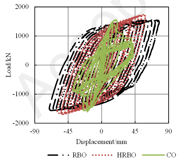
The yield load Py, the peak loads Pp, the yield displacement Dy, the peak displacements Dp and the ductility m of Specimen CO and Specimen RBO are shown in Table 1. Table 1 shows that the ductility of Specimen RBO has been increased by 56% compared with that of Specimen CO. However, the initial stiffness of Specimen RBO is slightly smaller than that of Specimen CO. Such smaller stiffness will be discussed in Section FE analysis of Specimen RBO.

Table 1. Comparison between the backbone curves of three specimens.

Specimens

Load /kN

Displacement /mm

m

Py

Pp

Dy

Dp

Du

CO

1359

1554

14.7

20

30

2.04

RBO

1170

1554

23.5

75

75

3.19

HRBO

1400

1754

34.2

60

60

1.75

Compared with Specimen CO, Specimen RBO has a much higher energy dissipation capacity and greater ductility (Figure 10(a)). However, the yield strength of Specimen RBO is smaller than Specimen CO, which is also smaller than the design requirement of the prototype outrigger. Thus, in order to increase the yield strength of Specimen RBO and delay the yielding in the sections of the chord, another specimen named Specimen HRBO was designed with high strength steel for the chords.

(a) Comparison of the hysteretic curves of three different specimens

(a) Comparison of the hysteretic curves of three different specimens

(b) The finally failure mode of Specimen HRBO

(b) The finally failure mode of Specimen HRBO

Figure 10. The results of Specimen HRBO.

Experimental observation and results of Specimen HRBO

Design of Specimen HRBO

Ban et al. (2011) indicated that the rupture elongation of the high strength steel whose yield stress exceeds 690 MPa commonly fails to meet the requirement of the design code. Thus, Q600 high strength steel was adopted in Specimen HRBO with a yield stress fy, a tensile strength fu and an ultimate elongation ¦Äd of 670 MPa, 780 MPa and 19%, respectively, from coupon tests. The properties of the steel met the requirement of the code of Chinese High Strength Low Alloy Structural Steels (GB1591-2008) (GAQSIQ, 2009). To ensure the comparability of the two specimens, the design and loading procedure of Specimen HRBO was the same as Specimen RBO.

Experimental results

When the loading displacement reached 15 mm, elongation deformation was observed in BRB II. Subsequently, when the loading displacement ranged from 20 mm to 60 mm, more deformation of BRBs was observed. The largest deformation of BRBs before the end of the test was 29.5 mm and 19.86 mm for the two members, respectively. Before the loading displacement reached 60 mm, neither the web nor the flange of RBS lost their stability. The loading procedure was stopped at 60 mm because local buckling occurred in the web and the flange of Section B of Chord I. Even after this point, the strength of Specimen HRBO still kept stable. The failure mode of Specimen HRBO is shown in Figure 10(b).

The load-displacement hysteretic curve of Specimen HRBO is shown in Figure 10(a). Figure 10(a) and Table 1 show that the yield strength and the peak strength of Specimen HRBO were increased by 20% and 13%, respectively, due to the use of high strength steel for chords. The yield strength is also greater than that of Specimen CO.

The comparison in Figure 10(a) shows that Specimen HRBO has significant ductility and energy dissipation capacity. Even though the peak displacement of Specimen HRBO was smaller than that of Specimen RBO, the ultimate story drift of Specimen HRBO reached 1/51 (60 mm / 3070 mm), which was much greater than the drift limit (1/100) specified in the Chinese Code for the Seismic Design of Buildings (GB5001-2010) (MOHURD, 2010). Thus, Specimen HRBO is also considered to have adequate deformation capacity for real buildings.

FE analysis of the specimens

Using the general-purpose FE program MSC. Marc (MSC.Software Corp. 2007), the three-dimensional FE model of the three specimens were created to reveal the failure mechanism, as shown in Figure 11. The shell elements and von Mises elasto-plastic model were adopted to simulate the steel members and the gusset plate. The BRBs were modeled using the truss elements in conjunction with the Chaboche constitutive model. The detailed discussion of the FE models of BRB is shown in Section Model calibration for BRB.

Figure 11. The FE model of three different specimens. Figure 11. The FE model of three different specimens.

(a)The FE model of Specimen CO.

(b)The FE model of Specimen RBO and Specimen HRBO

Figure 11. The FE model of three different specimens.

FE analysis of Specimen CO

Figure 12 shows the comparison between the experimental data and the FE results. The strength and the energy dissipation capacity were overestimated by the FE model if the effect of initial imperfection was not considered.

Figure12. The FE simulation of Specimen CO.

Figure12. The FE simulation of Specimen CO.

Thus, the initial imperfection should be considered in the FE model. The method proposed by Eurocode 3 (EN 1993-1:2005) to simulate the initial imperfection of members was adopted, as presented in Figure 13 and Equation 1.

                                                    (1)

where e0 is the initial imperfections; l is the member length. For the braces in Specimen CO, e0/l =1/350 according to Eurocode 3 (EN 1993-1:2005). q0 is the equivalent uniform forces; Nk is the design value of the compressive force. By adding q0 to the braces, the modified FE simulation results are compared to the test results in Figure 12. The FE simulation with initial imperfection agrees well with the test results.

Figure 13. The initial imperfection of components (EN 1993-1:2005)

Figure 13. The initial imperfection of components (EN 1993-1:2005).

1-The initial imperfection; 2-The equivalent uniform distributed load

FE analysis of Specimen RBO

Model calibration for BRB. Existing research (Wigle and Fahnestock, 2010; Rossi 2014) indicated that the Chaboche constitutive model had a high accuracy to model the cyclic stress-strain responses of metallic materials. Therefore, the simulation of the BRB was performed firstly using the truss element in conjunction with the Chaboche constitutive model. The simulation results of BRB agree well with the test results, as shown in Figure 7. Therefore, the truss elements and Chaboche constitutive model is  capable of simulating the complicated hysteresis behavior of BRBs.

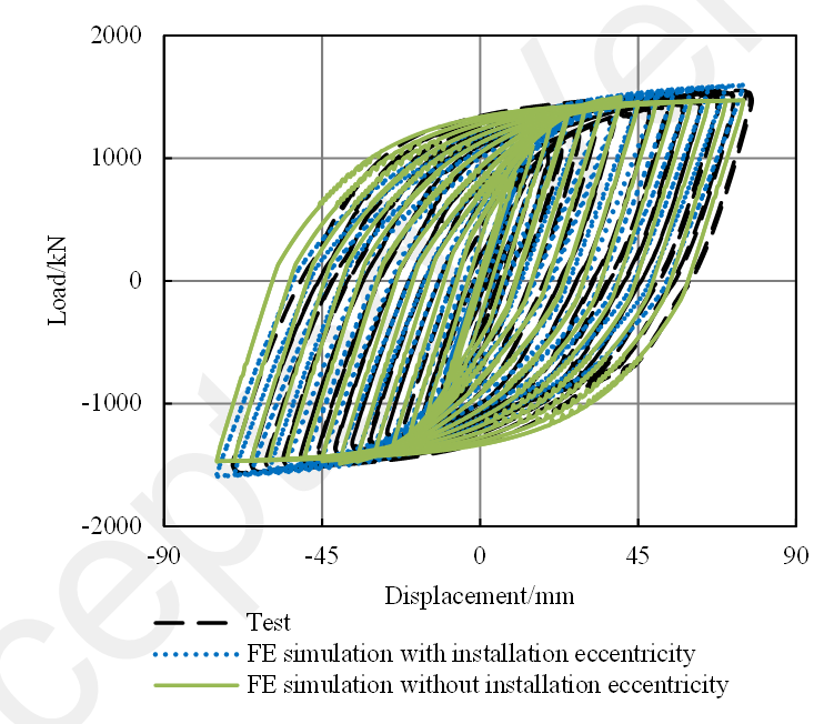
FE analysis of Specimen RBO. The Chaboche constitutive models and the truss elements validated above were thus used to simulate the BRBs in Specimen RBO. Due to the fact that the truss element is a one-dimensional element, the sectional dimension details cannot be represented using the truss element. Hence, for Specimen RBO, how to consider the installation eccentricity e0 of the BRB with a truss element is a challenge (Figure 14). The FE analysis indicated that the installation eccentricity e0 had minimal influence to the strength. But it would influence the initial stiffness to some extent, as shown in Figure 15. The simulated results had a slightly larger initial stiffness than the test results. Therefore, a rigid arm was added to the end of the truss element to consider the installation eccentricity e0. According to actual measurement, the installation eccentricity e0 was approximately 10mm. The hysteretic behavior accounting for the installation eccentricity e0 is shown in Figure 15, which agrees well with the experimental data.

Figure 14. The installation eccentricity.

Figure 14. The installation eccentricity.

Figure 15. The FE simulation of Specimen RBO.

Figure 15. The FE simulation of Specimen RBO.

FE analysis of Specimen HRBO

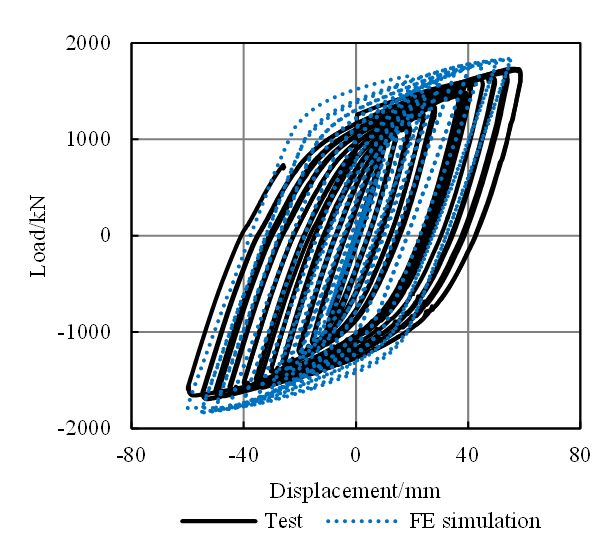
Specimen HRBO was simulated with the same FE model of Specimen RBO except for the steel strength of the chords. A comparison between the experimental data and the simulation results is presented in Figure 16, and it shows a good agreement.

Figure 16. The FE simulation of Specimen HRBO.

Figure 16. The FE simulation of Specimen HRBO.

The above comparisons indicate that the simulated hysteretic behaviors agree well with the experimental data, thus the developed FE models can be used to analyze the behavior and strength of outriggers.

Conclusions

This study analyzed the seismic performance of three different outriggers through pseudo-static tests and FE simulations. The conclusions are as follows:

(1) The test results of Specimen CO indicated that the failure modes were the global buckling of the braces and the local buckling of the chords after flexural yielding, which resulted in a steep deterioration of strength after peak and an unfavorable energy dissipation capacity.

(2) By using BRBs and RBSs in Specimen RBO, the buckling of braces was prevented, and the energy dissipation capacity and ductility of outriggers were significantly improved. However, the yield strength of Specimen RBO was smaller than that of Specimen CO.

(3) Specimen HRBO with high strength steel chords had higher yield and peak strengths, which fully satisfied the strength and deformation demands of the outriggers.

(4) FE models were developed to simulate the three specimens. The FE results showed good agreements with the test results. These models can be used for future analysis of outriggers with different chord and bracing configurations.

Acknowledgements

The authors are grateful for the financial support received from the Beijing Natural Science Foundation (No. 8142024).

References

Asai T, Chang CM, Phillips BM and Spencer BF (2013) Real-time hybrid simulation of a smart outrigger damping system for high-rise buildings. Engineering Structures 57: 177-188.

Ban HY, Shi G, Shi YJ and Wang YQ (2011) Research progress on the mechanical property of high strength structural steels. Advanced Materials Research 250: 640-648.

Black CJ, Makris N and Aiken ID (2004) Component testing, seismic evaluation and characterization of buckling-restrained braces. Journal of Structural Engineering 130(6): 880-894.

Chang CM, Wang Z, Spencer Jr BF and Chen Z (2013) Semi-active damped outriggers for seismic protection of high-rise buildings. Smart Structures and Systems 11(5): 435-451.

Chen YY, Wang B, Zhao XZ and Qin H (2013) Hysteretic tests on outrigger truss and its connection with mega column and core tube of the Shanghai Tower. Journal of Building Structures 34(2): 29-36. (in Chinese)

Canbolat BA, Parra-Montesinos GJ and Wight JK (2005) Experimental study on seismic behavior of high-performance fiber-reinforced cement composite coupling beams. ACI Structural Journal 102(1): 159-166.

Deng KL, Pan P, Lam A and Xue YT (2014) A simplified model for analysis of high-rise buildings equipped with hysteresis damped outriggers. The Structural Design of Tall and Special Buildings 23(15): 1158-1170.

Dan D, Fabian A and Stoian V (2011) Theoretical and experimental study on composite steel-concrete shear walls with vertical steel encased profiles. Journal of Constructional Steel Research 67(5): 800-813.

EN 1993-1-1 (2005) Eurocode 3: Design of steel structures. Part 1¨C1: general rules and rules for buildings. CEN Central Secretariat, Rue de Stassart 36, B-1050.

FEMA (2000) Recommended Seismic Design Criteria for New Steel Moment-Frame Buildings (FEMA-350), Federal Emergency Management Agency: Washington D.C.

GAQSIQ (2008) High Strength Low Alloy Structural Steels (GB1591-2008). General Administration of Quality Supervision, Inspection and Quarantine of the People¡¯s Republic of China: Beijing, China. (in Chinese)

Hoenderkamp JCD (2008) Second outrigger at optimum location on high-rise shear wall. The Structural Design of Tall and Special Buildings 17(3): 619-634.

Hitaka T and Matsui C (2003) Experimental study on steel shear wall with slits. Journal of Structural Engineering 129(5) 586-595.

Jiang HJ, Lu XL, Liu XJ and He LS (2014) Performance-based seismic design principles and structural analysis of Shanghai Tower. Advances in Structural Engineering 17(4): 513-528.

Kumar S, Itoh Y, Saizuka K and Usami T (1997) Pseudodynamic testing of scaled models. Journal of Structural Engineering 123(4): 524-526.

Kim NS, Kwak YH and Chang SP (2004) Pseudodynamic tests on small-scale steel models using the modified similitude law. In Proceedings of the 13th World Conference on Earthquake Engineering.

Li QS and Wu JR (2004) Correlation of dynamic characteristics of a super-tall building from full-scale measurements and numerical analysis with various finite element models. Earthquake Engineering and Structural Dynamics 33(14): 1311-1336.

Lu X, Lu XZ, Guan H and Ye LP (2013) Collapse simulation of reinforced concrete high-rise building induced by extreme earthquakes. Earthquake Engineering & Structural Dynamics 42(5): 705-723.

Lu X, Lu XZ, Sezen H and Ye LP (2014) Development of a simplified model and seismic energy dissipation in a super-tall building. Engineering Structures 67: 109-122.

Lu X, Lu XZ, Zhang WK and Ye LP (2011) Collapse simulation of a super high-rise building subjected to extremely strong earthquakes. Science China Technological Sciences 54(10): 2549-2560.

Lu XL, Zhou B, Zhao B and Lu WS (2015) Shaking table test and numerical analysis of a high-rise building with steel reinforce concrete column and reinforce concrete core tube, The Structural Design of Tall and Special Buildings 24(18): 1019-1038.

Lu XZ, Xie LL, Yu C and Lu X (2016) Development and application of a simplified model for the design of a super-tall mega-braced frame-core tube building. Engineering Structures 110: 116-126.

McNabb JW and Muvdi BB (1975) Drift reduction factors for belted high-rise structures. AISC Engineering Journal, 3rd Quarter: 88-91.

Moehle J (2015) Seismic design of reinforced concrete. McGraw-Hill Education.

MOHURD (2010) Code for the Seismic Design of Buildings (GB50011-2010). Ministry of Housing and Urban-Rural Development of the People¡¯s Republic of China: Beijing, China. (in Chinese)

MOHURD (2015) Specification for Seismic Test of Buildings (JGJ/T 101-2015). Ministry of Housing and Urban-Rural Development of the People¡¯s Republic of China, China. (in Chinese)

MSC. Software Corp. (2007) MSC. MARC. User¡¯s manual. MSC Software Corporation, Santa Ana, CA.

Nanduri PMBRK, Suresh B and Hussain MDI (2013) Optimum position of outrigger system for high-rise reinforced concrete buildings under wind and earthquake loadings. American Journal of Engineering Research 2(8): 76-89.

Naserifar A and Danesh F (2016) Experimental study on application of reduced section in long link-to-column connections. Advances in Structural Engineering 19(5): 795-805

Nie JG and Ding R (2013) Experimental research on seismic performance of K-style steel outrigger truss to concrete core tube wall joints. ASCE Structures Congress: 2802-2813.

O'Neill JC (2006) Application of damping in high-rise buildings. Doctoral dissertation, Massachusetts Institute of Technology.

Poon DCK, Hsiao LE, Zhu Y, Joseph L, Zuo S, Fu GY and Ihtiyar O (2011) Non-linear time history analysis for the performance based design of Shanghai Tower. ASCE Structures Congress: 541-551.

Rossi PP (2014) Importance of isotropic hardening in the modeling of buckling restrained braces. Journal of Structural Engineering 141(4): 1-11.

Smith BS and Coull A (1991) Tall building structures: analysis and design. University of Texas Press.

Smith RJ and Willford MR (2007) The damped outrigger concept for tall buildings. The Structural Design of Tall and Special Buildings 16(4): 501-517.

Taranath BS (1975) Optimum belt truss location for high-rise structures. Structural Engineer 53(8): 18-21.

Wigle VR and Fahnestock LA (2010) Buckling-restrained braced frame connection performance, Journal of Constructional Steel Research 66(1): 65-74

Youssef N, Wilkerson R, Fischer K and Tunick D (2010) Seismic performance of a 55-storey steel plate shear wall. The Structural Design of Tall and Special Buildings 19(1-2): 139-165.

Zhou Y and Li HX (2014) Analysis of a high-rise steel structure with viscous damped outriggers, The Structural Design of Tall and Special Buildings 23(13): 963-979.

Zhou Y, Lin SM, Wu CX and Deng XS (2012) Analysis of high-rise building with energy-dissipation story system. Proceedings of the 15th World Conference of Earthquake Engineering, Portugal.

Zhou Y, Zhang CQ and Lu XL (2014) Earthquake resilience of a 632-meter super-tall building with energy dissipation outriggers. Proceedings of the 10th National Conference in Earthquake Engineering, Earthquake Engineering Research Institute, Anchorage, AK, July, 2014

Zhao QH and Astaneh-Asl A (2004) Cyclic behavior of traditional and innovative composite shear walls. Journal of Structural Engineering 130(2): 271-284.


1 Department of Civil Engineering, Key Laboratory of Civil Engineering Safety and Durability of China Education Ministry, Tsinghua University, Beijing 100084, China

2 Department of Engineering Technology, University of North Texas, Denton, TX 76207, USA

3 Beijing Engineering Research Center of Steel and Concrete Composite Structures, Tsinghua University, Beijing 100084, China

*Corresponding author:

Xinzheng Lu, Department of Civil Engineering, Key Laboratory of Civil Engineering Safety and Durability of China Education Ministry, Tsinghua University, Beijing, P.R. China, E-mail: luxz@tsinghua.edu.cn

Introduction
Research
Application
Teaching
Publications
Download
Issues
Others


Our Lab

Collapse Prevention Committee