A high-performance quadrilateral flat shell element for seismic collapse simulation of tall buildings and its implementation in OpenSees

Xinzheng Lu1,*, Yuan Tian2, Song Cen3, Hong Guan4, Linlin Xie5, and Lisha Wang3

Journal of Earthquake Engineering,
Accepted on Jan. 24, 2017, DOI: 10.1080/13632469.2017.1297269.

1 Key Laboratory of Civil Engineering Safety and Durability of China Education Ministry, Department of Civil Engineering, Tsinghua University, Beijing, P.R. China, 100084

2 Beijing Engineering Research Center of Steel and Concrete Composite Structures, Tsinghua University, Beijing 100084, China

3 Department of Engineering Mechanics, School of Aerospace Engineering, Tsinghua University, Beijing, P.R. China, 100084

4 Griffith School of Engineering, Griffith University Gold Coast Campus, Queensland 4222, Australia

5 School of Civil and Transportation Engineering, Beijing University of Civil Engineering and Architecture, Beijing, P.R. China, 100044

Shear walls are important lateral-force resistant components of tall buildings. Hence, a reliable numerical model that can accurately represent the mechanical characteristics and large deformations of shear walls is critical for realistic collapse simulation of tall buildings. Based on the theory of generalized conforming element, a high-performance quadrilateral flat shell element, NLDKGQ, accounting for the large deformation using the updated Lagrangian formulation, is proposed herein and implemented in OpenSees. The reliability of NLDKGQ is validated using classical benchmark problems and reinforced concrete (RC) specimens. In addition, its capability in simulating the collapse of a tall building is also demonstrated.

Key words: flat shell element; OpenSees; shear wall; large deformation; collapse simulation.

1 Introduction

Recently, research on the seismic performance and collapse resistance of tall and super-tall buildings has become increasingly popular in earthquake engineering. The importance of these research efforts is evident, given the rapid growth of tall and super-tall building construction and an increased frequency of strong earthquakes. Research to date has indicated that numerical simulation using various finite element (FE) software packages is one of the most prevalent methods for the seismic performance analysis and collapse simulation of tall and super-tall buildings [Fan et al., 2009; Lu et al., 2011, 2013a, 2013b, 2016]. One such open source FE program, OpenSees, has been widely used to investigate the seismic performance of tall and super-tall buildings [Lu et al., 2015b], as well as super long span bridges [Lin et al., 2015]. The advantages of using OpenSees for seismic simulation have also been thoroughly discussed by Lu et al. [2015b]. OpenSees has also been adopted to conduct the collapse simulation of RC frames [Xie et al., 2015]. However, research on the collapse simulation of RC tall buildings using OpenSees has rarely been reported.

Beams, columns and shear walls are the primary components of RC tall buildings. To realistically simulate the collapse of RC tall buildings, the numerical model is required to have the capacity to accurately and reliably simulate the collapse behavior (which exhibits significant material and geometric nonlinearities, concurrently) of these components. Collapse simulations of beams and columns have been successfully conducted using OpenSees [Chen et al., 2008; Lignos et al., 2011; Xie et al., 2015]. The material nonlinearities of the shear walls have also been successfully simulated by the authors using the shell elements in OpenSees [Lu et al., 2015b], based on a previously self-developed multi-layered shell section model. However, the said shell element, i.e., the MITC4 shell element in OpenSees, has limited capacity for large deformation problems (i.e. geometric nonlinearity). As a result, such a shell element in OpenSees cannot be used to simulate the large deformation behavior of shear walls during the process of seismic collapse. Note that the collapse simulation of simple shear wall structures has been conducted in OpenSees by using the beam¨Ctruss model [Lu et al., 2014] and the modified multiple vertical line element model [Bao and Kunnath, 2010; Fischinger et al., 2012]. However, Lu et al. [2015b] has emphasized that the shell element is advantageous in investigating the seismic performance of complicated shear wall structures. Hence, a new and improved shell element is necessary to be developed to account for large deformations associated with the seismic collapse.

In addition to satisfying the demand of large deformations, several other demands are also required for the new shell element:

          (1)     The shear walls in a tall building are usually presented with various types of sections and shapes with complicated openings. The new shell element is expected to be highly adaptive for different types of shear walls. In addition, the element must be insensitive to mesh distortion and free from locking problems. It should be noted that an ideal mesh is not always possible for actual shear walls with irregular shape and openings.

          (2)     The geometric and material nonlinearities should be taken into consideration concurrently for the new shell element. This is critical for simulating the failure and collapse of shear walls.

          (3)     A balance between the modeling workload and computational accuracy must be considered. Specifically, the MITC4 shell element has 5 degrees of freedom (DOFs) per node while the beam/column element has 6 DOFs per node. When a shell element is connected to the beam/column elements directly, an embedded beam element along the boundary of the MITC4 shell element is normally required [Lu et al., 2015b]. Such an embedded element strategy results in additional modeling and computational efforts. To address this problem, the shell element should also be assigned 6 DOFs per node, which can greatly simplify the connection modeling between the shell elements and the beam/column elements.

          (4)     The new shell element should be adaptive to the overall framework of OpenSees, so that it can be implemented into OpenSees with minimal impact on the entire software.

To meet the above-mentioned demands, it is essential to choose an appropriate shell element type. In this study, the flat shell element is selected, owing to its satisfactory performance in the FE analysis [Long et al., 2009]. In addition, due to the simple and concise equations and geometric descriptions of the flat shell elements [Long et al., 2009], the large deformation algorithm can be conveniently developed and implemented. Several successfully developed flat shell elements [Madenci and Barut, 1994; Zhang et al., 1998; Zhang and Yang 2006] are proven to be free from mesh distortion and locking problems with acceptable modeling workload and satisfactory accuracy. However, several limitations of the currently available flat shell elements still remain:

          (1)     Most of the flat shell elements are triangular in shape. However, quadrilateral ones are normally preferred in earthquake engineering research due to their high performance in computation and reduced workload in modeling.

          (2)     Most of such elements have not taken the coupling effect of material and geometric nonlinearities into consideration.

Therefore, a novel high-performance quadrilateral flat shell element, the NLDKGQ element, is proposed and implemented in OpenSees in this work. The NLDKGQ element consists of a planar membrane element GQ12 [Xu and Long, 1993] and a plate bending element DKQ [Batoz and Tahar, 1982]. The GQ12 element is a high-performance quadrilateral membrane element, based on the theory of generalized conforming element by introducing rotational degrees of freedom at each node [Xu and Long, 1993]. The DKQ element, which is immune from locking problems, is a quadrilateral plate element with high accuracy and stability [Batoz and Tahar, 1982]. Given that the GQ12 element has two translational (along x and y) and one rotational (around z) DOFs per node, and the DKQ element has one translational (along z) and two rotational (around x and y) DOFs per node, the combination of these two elements makes the NLDKGQ element having 6 DOFs per node. Consequently, the NLDKGQ elements can be readily connected to the beam elements without introducing extra embedded beam elements, thereby greatly reducing the modeling workload. The geometric nonlinearity is further considered using an updated Lagrangian formulation [Belytschko et al., 2013]. The reliability of the NLDKGQ element for elastic small deformation and large deformation problems is validated using classical benchmark examples. Subsequently, typical RC specimens are simulated using the NLDKGQ element to validate its reliability in representing the complex mechanical behavior of the shear walls. Finally, an incremental dynamic analysis (IDA) is performed for a 42-story RC frame-core tube building with a height of 141.9 m to demonstrate the capability of the element in the collapse simulation of tall buildings. The research outcome is expected to provide an effective tool for further in-depth investigation of the collapse mechanisms of tall and super-tall buildings using OpenSees.

2 Formulation of the NLDKGQ element

2.1 Basic formulation under small deformation

The quadrilateral flat shell element NLDKGQ in the local coordinate system is shown in Figure 1.

Figure 1. DOFs of the NLDKGQ element in the local coordinate system

Figure 1. DOFs of the NLDKGQ element in the local coordinate system

The definition of the nodal displacement vector q (Figure 1) is:

           (1)

in which the nodal displacement components of the planar membrane element and the plate bending element are, respectively, represented by qim and qib  , as follows:

                                          (2)

                                                                                                  (3)

The displacement field u of GQ12 consists of the bilinear displacement field u0 and the additional rotation displacement field u¦È, which can be determined from the interpolation functions Ni0, Niuq, and Nivq [Xu and Long, 1993], as given in Equations 4 to 7.

                                                                                                                   (4)

                                          (5)

where

                           (6)

                                                    (7)

Then, the strain field em can be obtained from the derivative of the displacement field.

                                                                               (8)

where

                                                                                (9)

The stiffness matrix of the planar membrane element GQ12 is:

                                                                                               (10)

where Dmm denotes the material matrix of the planar membrane element. For isotropic linear elastic materials, Dmm is given in Equation 11, where h denotes the thickness of the element, and E and u denote the elastic modulus and Poisson¡¯s ratio, respectively.

                                                                                          (11)

Equation 3 presents the definition of the rotational DOFs of the DKQ element [Batoz and Tahar, 1982]. The relationship between the rotational strain fields cb and nodal displacements qb is:

                                                              (12)

where Hx and Hy are functions of Ni, xi and yi. Details about Equation 12 are provided by Batoz and Tahar [1982].

The stiffness matrix of the plate bending element DKQ is:

                                                                                                  (13)

where Dbb denotes the material matrix of the plate bending element. For isotropic linear elastic materials, Dbb has the following form.

                                                                                      (14)

Under the small deformation, the stiffness matrix of the NLDKGQ element in the local coordinate system can be obtained through the composition of the membrane and the plate stiffness matrices Km and Kb following the DOFs sequencing shown in Equation 1. The element stiffness matrix in the global coordinate system can be subsequently obtained after the coordinate transformation.

2.2 Geometric nonlinearity

Based on the deformation calculated at the current time step, the stresses and strains are updated in incremental forms using the updated Lagrangian formulation. According to Kirchhoff¡¯s and von Karman¡¯s assumptions [Podio-Guidugli, 1989], the strain increment of the shell element (De) can be separated into a linear part (De) and a nonlinear part (Dh). The linear part can be obtained from the composition of the membrane strain increment Dem and the plate rotational strain increment Dcb, which are presented in Equations 15 and 16.

                                                                                                             (15)

                                                                         (16)

From the current time step t to t+dt, the stress tensor of the shell element is updated according to Equation 17:

                                                                              (17)

where Dtan is the tangential constitutive matrix of the material at time t. Using the updated Lagrangian formulation, the system of equations of the shell element in the local coordinate system is:

                                                                                      (18)

where t+dtF denotes the external force vector at t+dt, and tR denotes the internal force vector at t. The linear part Kl and the nonlinear part Knl of the tangential stiffness matrix of the element are given in Equations 19 and 20.

                                                                        (19)

                                                                    (20)

where Dmm, Dmb, Dbm, and Dbb can be obtained through the integration of Dtan over the thickness of the element (Equation 21). The matrix G can be obtained from the interpolation function of the bending plate element according to its definition [Batoz and Tahar, 1982]. The matrix  is composed of variables corresponding to the internal force vector of the membrane element at time t (Equation 22).

                        (21)

                                                                     (22)

The elemental internal force vector tR given in Equation 18 can be calculated as follows:

                                                                                                  (23)

where

                                                                                    (24)

                                                                  (25)

2.3 Implementation in OpenSees

The formulation of the new shell element is added into OpenSees through the new class named ShellNLDKGQ, which is under the class of shell. The new element perfectly fits the framework of OpenSees without changing any source code beyond the shell element domain. The source code of the element can be downloaded from the official website of OpenSees (http://opensees.berkeley.edu).

3 Validation through classical benchmark problems

To validate the performance of the flat shell element NLDKGQ, several classical numerical benchmark problems are analyzed. For convenience of discussion, all parameters of these problems are made non-dimensional.

3.1 Pinched cylinder problem

The pinched cylinder problem, shown in Figure 2 [Belytschko and Leviathan, 1994], has been widely used to benchmark the performance of various shell elements. Due to the symmetrical conditions, only one-eighth of the cylinder is modeled, meshed and analyzed. The corresponding results are shown in Table 1. In this problem, three types of shell elements are compared, namely the 4-node quadrilateral element S4 in ABAQUS [Dassault Syst¨¨mes Simulia Corp., 2009], MITC4 in OpenSees [Dvorkin and Bathe, 1984], and the proposed flat shell element NLDKGQ. For all three types of shell elements, the geometric nonlinearity is not considered. Table 1 shows that the accuracy of the NLDKGQ element is higher than that of the other two shell elements, especially when the mesh is coarse. This advantage of the NLDKGQ element is very critical for the simulation of tall buildings consisting of thousands of structural components, because a very fine mesh requiring large amount of computational workload is impractical and unacceptable.

Figure 2. Description of the pinched cylinder problem

Figure 2. Description of the pinched cylinder problem

Table 1. Normalized results for the pinched cylinder problem

Element

Mesh

4¡Á4

8¡Á8

16¡Á16

S4 in ABAQUS

0.382

0.742

0.918

MITC4 in OpenSees

0.344

0.717

0.910

NLDKGQ in OpenSees

0.629

0.935

0.999

Theoretical solution

1.000a

1.000a

1.000a

a The theoretical solution is 1.8541¡Á10-5 [Belytschko and Leviathan, 1994]

3.2 MacNeal¡¯s beam problem

The MacNeal¡¯s beam problem [MacNeal and Harder, 1985] is a classical benchmark to test the mesh distortion sensitivity of 4-node quadrilateral elements. Three different meshes are adopted: (a) rectangular, (b) parallelogram and (c) trapezoid, as shown in Figure 3. Pure bending and transverse loading cases are analyzed. Geometric nonlinearity is not considered in this case. In addition to the NLDKGQ elements, the normalized results obtained from other types of elements are also given for comparison, as summarized in Table 2. Both the NLDKGQ and the S4 elements are free from mesh distortion and membrane locking problems and their predictions are of similar accuracy; whereas serious membrane locking problems are encountered by the MITC4 elements in OpenSees and the Q4 [Shi and Voyiadjis, 1991]. Note that a similar phenomenon associated with the MITC4 element was also found by Cardoso et al. [2006]. This comparison confirms the advantage of NLDKGQ in simulating the beams with irregular meshes.

Figure 3. Description of the MacNeal¡¯s slender beam problem

Figure 3. Description of the MacNeal¡¯s slender beam problem

3.3 Large deformation problem of a cantilever beam

A cantilever beam subjected to a pure bending load (out-of-plane) is analyzed to validate the capacity of the NLDKGQ element in modeling large deformations (geometric nonlinearity), as shown in Figure 4. The commonly used mesh of 1´10 is adopted [Horrigmoe and Bergan, 1978; Park et al., 1995]. Figure 5(a) shows the relationship between the normalized moment (k=M/Mmax) and the horizontal and vertical displacements at the loading point. Figure 5(b) shows the deformed shape of the cantilever beam under different bending moments. The results show that the NLDKGQ element can simulate the large deformation and rotation problems with good accuracy, which is similar to the S4 element in ABAQUS. Such a large deformation capacity makes the NLDKGQ element highly suitable for the collapse simulation of tall buildings. Note that the MITC4 element in OpenSees fails to simulate this problem accurately even when k is small, due to its limited capacity in modeling large deformations. It should also be noted that the same model using the MITC4 element fails to converge when k reaches 0.4485.

Table 2. Normalized results for the MacNeal¡¯s slender beam problem

Element

Load P

Load M

Mesh (a)

Mesh (b)

Mesh (c)

Mesh (a)

Mesh (b)

Mesh (c)

Q4

0.093

0.035

0.003

0.093

0.031

0.022

S4 in ABAQUS

0.907

0.876

0.874

0.915

0.890

0.889

MITC4 in OpenSees

0.076

0.030

0.030

0.076

0.028

0.028

NLDKGQ in OpenSees

0.904

0.875

0.872

0.910

0.881

0.881

Theoretical solution

1.000a

1.000a

1.000a

1.000b

1.000b

1.000b

a The theoretical value is -0.1081. b The theoretical value is -0.0054.

Figure 4. A cantilever beam subjected to a bending moment at the end

Figure 4. A cantilever beam subjected to a bending moment at the end

(a) Displacement of the loading point

(u and w are the displacements in the x and z directions, respectively)

(b) Deformed shape of the cantilever beam

Figure 5. Deformation of the cantilever beam

4 Validation through analysis of RC specimens

4.1 RC shear wall experiments

To investigate the performance of the NLDKGQ element in simulating RC specimens, the multi-layered shell section model [Lu et al., 2015b] is used herein. Details of this section model in OpenSees are provided by Lu et al. [2015b] and the corresponding command lines are given in Appendix B. In general, concrete is assumed to be in a state of planar stress in the multi-layered shell element. The analytical model for concrete is based on the concept of damage mechanics and the smeared crack model. The reinforcing bars are simulated as smeared steel layers of equivalent thicknesses. The material model for reinforcing steel, designated as PlateRebar, is derived from the uniaxial materials for rebars in conjunction with their corresponding angles with respect to the Cartesian coordinate.

Based on the multi-layered shell section model [Lu et al., 2015b] and the NLDKGQ element, four shear wall specimens are analyzed using OpenSees to investigate the performance of the NLDKGQ element in simulating the hysteretic behavior of the RC shear walls. The test specimens include two rectangular walls [Zhang, 2007], one flanged wall [Chen and Qian, 2005], and one coupled wall [Chen and Lu, 2003]. The element mesh recommended by Lu et al. [2015b] is used. The simulation results predicted by the MITC4 element are also presented for comparison. The lateral force versus top displacement hysteretic curves shown in Figure 6 indicate that both the NLDKGQ and the MITC4 elements perform satisfactorily against the test results.

(a) SW1-1

(b) SW2-1

(c) SW-4

(d) CW-3

Figure 6. Lateral force versus top displacement hysteretic curves of RC shear walls

4.2 A pseudo-static collapse experiment of an RC column

Most RC shear wall experiments are limited to small deformations. To validate the performance of the NLDKGQ element for RC components under large deformations, a pseudo-static collapse experiment of an RC column [Xie et al., 2015] is simulated herein. Column B tested by Xie et al. [2015] is modeled with the MITC4 and NLDKGQ elements using the same mesh strategy and same multi-layered shell section. Figure 7 shows the loading condition of Column B. The column is meshed with 15 (along height) ´ 4 (along width) elements. Figure 8 shows the comparison of the hysteretic curves. It is evident that, the MITC4 element fails to simulate the collapse characteristics of Column B because of its locking problems and limited capacity to simulate large deformations. In contrast, the NLDKGQ element can accurately simulate the strength degradation due to large deformations.

Figure 7. Loading condition of Column B

Figure 8. Comparison of hysteretic curves

5 IDA of an RC frame-core tube tall building

As described in Sections 3 and 4, the accuracy and reliability of the proposed NLDKGQ element have been validated. In this section, the proposed element is used for the collapse simulation of a typical tall building. In this work, a 42-story RC frame-core tube building (Figure 9) with a height of 141.9 m (denoted as Building 2N by Lu et al. [2015a]) is simulated using OpenSees. More details about this building can be found in Lu et al. [2015a]. Note that the element mesh of this building is further refined compared with that in Lu et al. [2015a] to better represent the local failure of shear walls during the collapse procedure. The IDA of this tall building is performed to demonstrate the collapse simulation capacity of the NLDKGQ element. Two FE models are established for comparison, i.e., ¡°Building 2N-NLDKGQ¡± (the shear wall is meshed with the NLDKGQ element) and ¡°Building 2N-MITC4¡± (the shear wall is meshed with the MITC4 element). In general, it is rather challenging to establish a complicated tall building model in OpenSees directly. Hence a conversion program, named MSC.Marc to OpenSees [Lu et al., 2015b], is used herein. The modeling strategy is as follows. The DispBeamColumnelement in OpenSees is adopted to simulate the beams and columns using fiber sections. The multi-layered shell elements (i.e. ShellMITC4 and ShellNLDKGQ) are used to simulate the shear walls, core tubes and coupling beams. The rigidDiaphragm is used to simulate the slabs. The Rayleigh damping consisting of mass and current stiffness matrix is adopted. The analysis domain recommended by Lu et al. [2015b] is adopted, as given in Table 3. A comparison between the fundamental periods predicted by using the MITC4 and NLDKGQ elements is presented in Table 4. The comparison indicates that both models exhibit similar basic dynamic properties at the elastic stage.

Figure 9. Three-dimensional view and typical layout of Building 2N (unit: mm)

Table 3. Analysis domain used for Building 2N

The command to assign boundary constraints

The command to assign a matrix solver

The command to assign an eigen value solver

Transformation

CuSP

ProfileSPD

Table 4. Comparison of the periods predicted by the MITC4 and NLDKGQ elements


Building 2N-

MITC4

Building 2N-

NLDKGQ

T1 /s (1st-order translation in X direction)

2.643

2.720

T2 /s (1st-order translation in Y direction)

2.386

2.524

T3 /s (1st-order torsion)

1.979

2.095

Note that the results of modal analysis in Table 4 are lower than the results of a similar US design (denoted as ¡°Building 2A¡±) provided by Moehle et al. [2011]. There are two main reasons for the shorter design period of Building 2N: (1) Moehle et al. [2011] used effective component stiffness values to predict the vibration period; while the elastic stiffness values are used herein following the Chinese design codes. (2) The basement is included in the analysis model of Building 2A [Moehle et al., 2011], which also lengthened the design periods. Regardless of the above two reasons, if the periods of Building 2A are calculated using the same method for Building 2N without including the basement, the elastic fundamental period of Building 2A is approximately 2.9 s. This value is similar to the translational period of the models established in this work. More details have been discussed by Lu et al. [2015a].

For tall buildings, high-order vibration modes in general contribute largely to the seismic responses. Therefore, performing a pushover analysis for tall buildings may not be considered appropriate [Krawinkler and Seneviratna, 1998; Fajfar, 2000; Chopra and Goel, 2002; Jan et al., 2004]. The nonlinear time history analysis, which is more suitable for tall buildings, is thus conducted in this study. Note that the P-Delta effect is also considered in the analysis. To validate the models in OpenSees, a careful comparison of the simulation results predicted by OpenSees and a well validated commercial software MSC.Marc [MSC Software, 2007] is conducted, and the results are shown in Figure 10. In the time history analysis, the widely used El-Centro 1940 ground motion is input to the structure along the X-direction after the gravity analysis is completed. Two peak ground accelerations (PGA) are chosen here, including 110 cm/s2 and 510 cm/s2 (63.2% and 2% probability of exceedance at the 50-year hazard level of this building defined in the Chinese code [CMC, 2010]). It can be seen that, the results agree well at both elastic and nonlinear stages, confirming the reliability of the models being implemented in OpenSees.

In the IDA, the El-Centro 1940 ground motion is also used as input to the structure along the X-axis after the gravity analysis is completed. Several typical PGAs are considered, including 510 cm/s2, 2000 cm/s2, 4000 cm/s2, 5000 cm/s2, and 6000 cm/s2. Note that such an IDA for tall buildings is very time consuming if it is implemented with the CPU-based matrix solvers in OpenSees. Thus, a graphics processing unit (GPU)-based matrix solver (i.e., solver CuSP) is developed to accelerate the simulation process. Details of the GPU-based solver are presented in Appendix A. It should also be noted that, in this study, elemental deactivation technology is not used. In the collapse simulation, the stress and stiffness of the materials (steel and concrete) are considered to decrease with increased deformation after the peak point, following the material constitutive law. In consequence, when the deformation is large enough, the stress and stiffness of the materials are approaching zero. For instance, the concrete strength reaches zero when the strain of concrete fibers/layers is greater than the ultimate strain. Such modeling technique has proven to successfully simulate the collapse behavior together with the geometric nonlinearity of the finite element model. The envelopes of the inter-story drifts at different PGAs are shown in Figure 11 for Building 2N-NLDKGQ and Building 2N-MITC4. The relationship between the PGA and the corresponding maximum inter-story drift ratio is illustrated in Figure 12. With respect to the inter-story drift ratios, Villaverde [2007] summarized a number of methods in assessing the seismic collapse capacity of buildings and concluded that in the incremental dynamic analysis (IDA), ¡°the global collapse capacity is considered reached when the curve in this plot becomes flat¡±. In general, 20% of the initial slope is adopted as the criterion for defining the ¡°flat¡± curve [FEMA, 2000; Jalayer, 2003; Riahi et al., 2015]. From the IDA curve shown in Figure 12, this criterion is satisfied when the inter-story drift ratio is greater than 7%. The corresponding collapse mode of Building 2N-NLDKGQ at the PGA level of 6000 cm/s2 is displayed in Figure 13.

(a) El-Centro 110cm/s2

(b) El-Centro 510cm/s2

Figure 10.      Comparison of the time history analysis results

(a) Building 2N-NLDKGQ

(b) Building 2N-MITC4

Figure 11.      The envelope of the inter-story drift curves

Figure 12.      The relationship between PGA and the maximum inter-story drifts

The comparisons given in Figures 11 and 12 reveal that Building 2N-NLDKGQ and Building 2N-MITC4 present similar results when the displacement is small (i.e., the maximum inter-story drift is smaller than 2% when PGA is smaller than 4000 cm/s2). However, a significant difference can be observed when the structures undergo large deformations and when collapse occurs under the strong ground motion (i.e., PGA is greater than 4000 cm/s2). Considerable deformations taking place at the bottom 5 stories of Building 2N-NLDKGQ (Figure 13) signify the collapse of the building under large deformations. Such a collapse behavior cannot be predicted by the MITC4 element, as indicated by the continuously increasing IDA curve (Figure 12) of Building 2N-MITC4, even under the excessive ground motion. This outcome is no doubt unreasonable.

Figure 13.      Typical collapse mode of Building 2N-NLDKGQ at a PGA of 6000 cm/s2 (with the displacement scale factor of 1.0) (unit: m)

6 Conclusions

In this work, a high-performance quadrilateral flat shell element NLDKGQ is proposed based on the theory of generalized conforming element and updated Lagrangian formulation. Through the analysis of the classical benchmark problems and the typical experiments of RC specimens, the performance of the proposed element is validated. Furthermore, the collapse simulation of an RC frame-core tube building with a height of 141.9 m is successfully conducted using the proposed element. The following conclusions are drawn.

          (1)     The NLDKGQ element is perfectly adaptive to the framework of OpenSees and can be conveniently added to the software.

          (2)     The NLDKGQ element is insensitive to mesh distortion and free from locking problems. In addition, it can concurrently consider the geometric and material nonlinearities, and produce accurate solutions to geometric and material nonlinear problems.

          (3)     In combination with the multi-layered shell section model, the NLDKGQ element can accurately simulate the nonlinear behavior of RC specimens and perform better than the MITC4 element in OpenSees when the RC specimens undergo large deformations.

          (4)     The NLDKGQ element can be used to simulate large deformations and collapse behavior of typical RC tall buildings. This simulation cannot be performed in OpenSees without the NLDKGQ elements.

The high-performance quadrilateral flat shell element NLDKGQ proposed in this work is expected to provide an effective tool and a useful reference for further in-depth investigation of the collapse mechanisms of tall and super-tall buildings using OpenSees.

Acknowledgements

The authors would like to acknowledge the financial supports of the National Natural Science Foundation of China (Nos. 11272181, 51261120377), the Specialized Research Fund for the Doctoral Program of Higher Education of China (No. 20120002110080), and the Tsinghua University Initiative Scientific Research Program (Project No. 2014z09099). The authors are also grateful for Prof. Quan Gu for his help in adding the source code of this new element into OpenSees.

References

Bao, Y. and Kunnath, S. K. [2010] ¡°Simplified progressive collapse simulation of RC frame-wall structures,¡± Engineering Structures 32(10), 3153-3162.

Batoz, J. L. and Tahar, M. B. [1982] ¡°Evaluation of a new quadrilateral thin plate bending element,¡± International Journal for Numerical Methods in Engineering 18(11), 1655-1677.

Belytschko, T. and Leviathan, I. [1994] ¡°Physical stabilization of the 4-node shell element with one point quadrature,¡± Computer Methods in Applied Mechanics and Engineering 113(3), 321-350.

Belytschko, T., Liu, W. K., Moran, B. and Elkhodary, K. [2013] Nonlinear finite elements for continua and structures. John Wiley & Sons.

Cardoso, R. P. R., Yoon, J. W., and Valente, R. A. F. [2006] ¡°A new approach to reduce membrane and transverse shear locking for one-point quadrature shell elements: linear formulation,¡± International Journal for Numerical Methods in Engineering 66(2), 214-249.

Chen, Q. and Qian, J. R. [2005] ¡°Static elasto-plastic analysis of RC shear walls with one row opening,¡± Chinese Journal of Computational Mechanics 22(1), 13-19. [in Chinese]

Chen, X. W., Han, X. L., Jack, C., Lin, S.Y. and Mao, G.N. [2008] ¡°Dynamic inelastic numerical simulation for a shaking table test of a full scale steel moment frame structure based on OpenSEES,¡± Proc. of the 14th World Conference on Earthquake Engineering, Beijing, China.

Chen, Y. T. and Lu, X. L. [2003] ¡°Seismic behavior of coupled shear walls-experiment and theoretical analysis,¡± Journal of Building Structures 24(4), 25-34. [in Chinese]

Chopra, A. K., and Goel, R. K. [2002] ¡°A modal pushover analysis procedure for estimating seismic demands for buildings,¡± Earthquake Engineering & Structural Dynamics 31(3), 561-582.

CMC. [2010] Code for Seismic Design of Buildings (GB50011-2010), China Ministry of Construction; China Architecture and Building Press, Beijing, China. [in Chinese]

Dassault Syst¨¨mes Simulia Corp.. [2009] Abaqus Theory Manual. Abaqus 6.9 HTML Documentation. http://abaqusdoc.ucalgary.ca/v6.9/books/stm/default.htm

Dvorkin, E. N. and Bathe, K. J. [1984] ¡°A continuum mechanics based four-node shell element for general non-linear analysis,¡± Engineering computations 1(1), 77-88.

Fajfar, P. [2000] ¡°A nonlinear analysis method for performance-based seismic design,¡± Earthquake spectra 16(3), 573-592.

Fan, H., Li, Q. S., Tuan, A. Y. and Xu, L. [2009] ¡°Seismic analysis of the world¡¯s tallest building,¡± Journal of Constructional Steel Research 65, 1206-1215.

FEMA. [2000] ¡°Recommended seismic design criteria for new steel moment frame buildings,¡± Publ. No. 350, Washington, D.C.

Fischinger, M., Rejec, K. and Isaković, T. [2012] ¡°Modeling inelastic shear response of RC walls,¡± Proc. of the 15th World Conference on Earthquake Engineering, Lisboa.

Horrigmoe, G. and Bergan, P. G. [1978] ¡°Nonlinear analysis of free-form shells by flat finite elements,¡± Computer Methods in Applied Mechanics and Engineering 16, 11-35.

Jan, T. S., Liu, M. W., and Kao, Y. C. [2004] ¡°An upper-bound pushover analysis procedure for estimating the seismic demands of high-rise buildings,¡± Engineering Structures 26(1), 117-128.

Jalayer, F. [2003] ¡°Direct probabilistic seismic analysis: implementing nonlinear dynamic assessments,¡± PhD. Dissertation, Department of Civil Engineering, Stanford University.

Krawinkler, H., and Seneviratna, G. [1998] ¡°Pros and cons of a pushover analysis of seismic performance evaluation,¡± Engineering structures 20(4), 452-464.

Lignos, D. G., Chung, Y., Nagae, T. and Nakashima, M. [2011] ¡°Numerical and experimental evaluation of seismic capacity of high-rise steel buildings subjected to long duration earthquakes,¡± Computers & Structures 89(11), 959-967.

Long, Y. Q., Cen, S. and Long, Z. F. [2009] Advanced finite element method in structural engineering, Tsinghua University Press.

Lin, K. Q., Xie, L. L., Lu, X. Z. and Ye, L. P. [2015] ¡°Earthquake-induced collapse simulation of a super-long span cable-stayed bridge based on an open source FE program,¡± Proc. of IABSE Conference-Structural Engineering: Providing Solutions to Global Challenges, Geneva, Switzerland.

Lu, X., Lu, X. Z., Zhang, W. K. and Ye, L. P. [2011] ¡°Collapse simulation of a super high-rise building subjected to extremely strong earthquakes,¡± Science China Technological Sciences 54(10), 2549-2560.

Lu, X., Lu, X. Z., Guan, H. and Ye, L. P. [2013a] ¡°Collapse simulation of reinforced concrete high-rise building induced by extreme earthquakes,¡± Earthquake Engineering & Structural Dynamics 42(5), 705-723.

Lu, X. Z., Lu, X., Guan, H., Zhang, W.K. and Ye, L. P. [2013b] ¡°Earthquake-induced collapse simulation of a super-tall mega-braced frame-core tube building,¡± Journal of Constructional Steel Research 82, 59-71.

Lu, X. Z., Li, M. K., Guan, H., Lu, X. and Ye, L. P. [2015a] ¡°A comparative case study on seismic design of tall RC frame-core-tube structures in China and USA,¡± The Structural Design of Tall and Special Buildings 24(9), 687-702.

Lu, X. Z., Xie, L. L., Guan, H., Huang, Y. L. and Lu, X. [2015b] ¡°A shear wall element for nonlinear seismic analysis of super-tall buildings using OpenSees,¡± Finite Elements in Analysis and Design 98, 14-25.

Lu, X., Lu, X. Z., Guan, H., and Xie, L. L. [2016] ¡°Application of earthquake-induced collapse analysis in design optimization of a supertall building,¡± The Structural Design of Tall and Special Buildings 25(17), 926¨C946. DOI: 10.1002/tal.1291.

Lu, Y., Panagiotou, M. and Koutromanos, I. [2014] ¡°Three-dimensional beam-truss model for reinforced-concrete walls and slabs subjected to cyclic static or dynamic loading,¡± Pacific Earthquake Engineering Research Center, Los Angeles, California.

MacNeal, R. H. and Harder, R. L. [1985] ¡°A proposed standard set of problems to test finite element accuracy,¡± Finite Elements in Analysis and Design 1(1), 3-20.

Madenci, E. and Barut, A. [1994] ¡°A free-formulation-based flat shell element for non-linear analysis of thin composite structures,¡± International Journal for Numerical Methods in Engineering 37(22), 3825-3842.

Moehle, J., Bozorgnia, Y., Jayaram, N., Jones, P., Rahnama, M., Shome, N., Tuna, Z., Wallace, J., Yang, T., and Zareian, F. [2011] ¡°Case Studies of the Seismic Performance of Tall Buildings Designed by Alternative Means,¡± Pacific Earthquake Engineering Research Center, University of California, Berkeley, California, USA, July.

MSC Software. [2007] Marc 2007 r1 User's Guide, MSC Software, Santa Ana, CA.

NVIDIA. [2014a] CuSP Home Page. http://cusplibrary.github.io/.

NVIDIA. [2014b] CUDA C programming guide, http://docs.NVIDIA.com/cuda/pdf/CUDA_C_Programming_Guide.pdf; Date accessed: May 2016.

Park, H. C., Cho, C. and Lee, S. W. [1995] ¡°An efficient assumed strain element model with six DOF per node for geometrically non-linear shells,¡± International Journal for Numerical Methods in Engineering 38(24), 4101-4122.

PEER. [2014] Subversion Repositories, http://opensees.berkeley.edu/WebSVN/listing.php?repname=OpenSees&path=%2Ftrunk%2FSRC; Date accessed: May 2016.

Podio-Guidugli P. [1989] ¡°An exact derivation of the thin plate equation,¡± Journal of Elasticity 22(2-3), 121-133.

Riahi, H.T., Amouzegar, H., and Falsafioun, M. [2015] ¡°Seismic collapse assessment of reinforced concrete moment frames using endurance time analysis,¡± The Structural Design of Tall and Special Buildings 24(4), 300-315.

Shi, G. and Voyiadjis, G. Z. [1991] ¡°Efficient and accurate four-node quadrilateral C0 plate bending element based on assumed strain fields,¡± International Journal for Numerical Methods in Engineering 32(5), 1041-1055.

Villaverde, R. [2007] ¡°Methods to assess the seismic collapse capacity of building structures: State of the art,¡± Journal of Structural Engineering, ASCE, 133(1), 57-66.

Xie, L. L., Lu, X. Z., Guan, H. and Lu, X. [2015] ¡°Experimental study and numerical model calibration for earthquake-induced collapse of RC frames with emphasis on key columns, joints and overall structure,¡± Journal of Earthquake Engineering 19(8), 1320-1344.

Xu, Y. and Long, Y. Q. [1993] ¡°Quadrilateral membrane element with vertex rotational freedom from generalized compatible condition,¡± Engineering Mechanics 10(3), 27-36. [in Chinese]

Xu, Z., Lu, X. Z., and Law, K. H. [2016] ¡°A computational framework for regional seismic simulation of buildings with multiple fidelity models,¡± Advances in Engineering Software 99, 100-110.

Zhang, H. M. [2007] ¡°Study on the performance-based seismic design method for shear wall structures,¡± Ph.D. thesis, Tongji University, Shanghai, China. [in Chinese]

Zhang, Q., Lu, M. and Kuang, W. Q. [1998] ¡°Geometric nonlinear analysis of space shell structures using generalized conforming flat shell elements-for space shell structures,¡± Communications in Numerical Methods in Engineering 14(10), 941-957.

Zhang, Y. X. and Yang, C. H. [2006] ¡°A family of simple and robust finite elements for linear and geometrically nonlinear analysis of laminated composite plates,¡± Composite Structures 75(1), 545-552.

Appendix A. GPU-based Matrix Solvers in OpenSees

A new GPU-based parallel solver for the sparse systems of equations (SOEs) is developed and added to OpenSees, namely CuSP solver [Xu et al., 2016]. The matrix algorithm of CuSP solver is based on CuSP [NVIDIA, 2014a], a GPU-accelerated numerical library for the sparse SOEs developed by Compute Unified Device Architecture (CUDA) [NVIDIA, 2014b]. The CuSP solver is developed based on the following rules:

          (1)     The iterative algorithms (i.e., the conjugate gradient (CG) algorithm, Bi-CG algorithm and generalized minimal residual (GMRES) algorithm) are used to maximize the parallel computing ability of the GPU.

          (2)     The Solver class (corresponding to the LinearSOESolver class of OpenSees) and the solving function are designed separately. The Solver class is designed inheriting the LinearSOESolver class, to improve the compatibility of the solver.

          (3)     The kernel algorithm of CuSP solver is packaged in the form of a dynamic-link library (DLL), which is convenient to be updated without changing the framework of OpenSees.

Figure A.1 illustrates the specific solving process of CuSP solvers. The matrix is integrated in CPU, and then copied into the graphics memory to perform the parallel computation. Finally, the results are returned into CPU for subsequent computation.

The corresponding source codes of CuSP solver are available at the website of OpenSees [PEER, 2014].
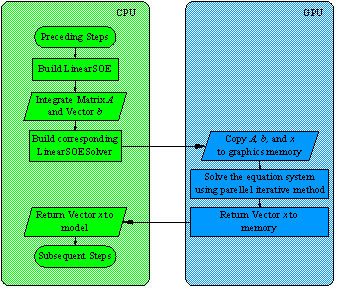
Figure A.1.    Flow chart of GPU-based solvers for the sparse SOEs

Appendix B. Command lines to implement the multi-layered shell element and NLDKGQ element

The two-dimensional concrete material is introduced to the model through the following command lines as

nDMaterial PlaneStressUserMaterial  $matTag  40  7  $fc  $ft  $fcu  $epsc0  $epscu  $epstu  $stc

$matTag

Integer tag identifying material

$fc

Concrete compressive strength (positive)

$ft

Concrete tensile strength (positive)

$fcu

Concrete ultimate strength (negative)

$epsc0

Concrete strain at maximum strength (negative)

$epscu

Concrete strain at ultimate strength (negative)

$epstu

Ultimate tensile strain (positive)

$stc

Shear retention factor

nDMaterial PlateFromPlaneStress $newmatTag  $matTag  $OutofPlaneModulus

$newmatTag

New integer tag identifying material deriving from pre-defined PlaneStressUserMaterial

$matTag

Integer tag identifying PlaneStressUserMaterial

$OutofPlaneModulus

Out-of-plane shear modulus

The reinforcing steel material for the multi-layered shell element is introduced to the model through the following command line as

nDMaterial PlateRebar  $newmatTag  $matTag  $sita

$newmatTag

New integer tag identifying material deriving from pre-defined uniaxial steel material

$matTag

Integer tag identifying uniaxial steel material

$sita

Define the angle of steel layer, 90¡ã (longitudinal steel), 0¡ã (transverse steel)

The multi-layered shell section is defined through the following command line as

section LayeredShell  $sectionTag  $nLayers  $matTag1  $thickness1 ¡­ $matTagn  $thicknessn

$sectionTag

Unique tag among sections

$nLayers

Total numbers of layers

$matTag1

Material tag of first layer

$thickness1

Thickness of first layer

¡­


$matTagn

Material tag of last layer

$thicknessn

Thickness of last layer

The NLDKGQ shell element is defined through the following command line as

element ShellNLDKGQ $eleTag $iNode $jNode $kNode $lNode $secTag

$eleTag

Unique element object tag

$iNode $jNode $kNode $lNode

Four nodes defining element boundaries, input in clockwise or counter-clockwise order around the element.

$secTag

Tag associated with previously-defined SectionForceDeformation object.


* Address correspondence to Xinzheng Lu, Department of Civil Engineering, Tsinghua University, Beijing, P.R. China. E-mail: luxz@tsinghua.edu.cn

Introduction
Research
Application
Teaching
Publications
Download
Issues
Others


Our Lab

Collapse Prevention Committee